Hyundai Ioniq (AE): Crash Pad / Main Crash Pad Assembly. Repair procedures
Hyundai Ioniq (AE) 2017-2022 Service & Repair Manual / Body (Interior and Exterior) / Crash Pad / Main Crash Pad Assembly. Repair procedures
| Replacement |
|

| 1. | Disconnect the negative (-) battery terminal. |
| 2. | Remove the front pillar trim (Refer to Interior Trim - "Front Pillar Trim") |
| 3. | Remove the floor console assembly. (Refer to Floor Console - "Floor Console Assembly") |
| 4. | Remove the center fascia panel. (Refer to Crash Pad - "Center Fascia Panel") |
| 5. | Remove the AVN head unit. (Refer to Body Electrical System - "AVN Head Unit") |
| 6. | Remove the crash pad garnish. (Refer to Crash Pad - "Crash Pad Garnish") |
| 7. | Remove the glove box upper cover assembly. (Refer to Crash Pad - "Glove Box Upper Cover Assembly") |
| 8. | Remove the steering wheel. (Refer to Steering System - "Steering Wheel") |
| 9. | Remove the steering column shroud lower panel. (Refer to Crash Pad - "Steering Column Shroud Panel") |
| 10. | Remove the multifunction switch assembly. (Refer to Body Electrical System - "Multifunction Switch") |
| 11. | Remove the instrument cluster. (Refer to Body Electrical System - "Instrument Cluster") |
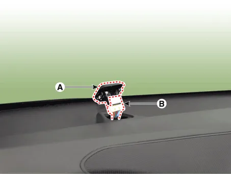
| 12. | Using a remover, remove the photo sensor (A) and separate the photo sensor connector (B).
|
| 13. | Loosen the mounting screws and remove the center duct (A).
|

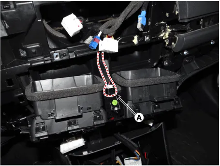
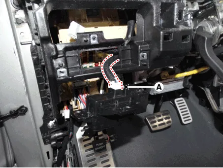
| 14. | Press the lock pin and separate the harzard switch connector (A).
|
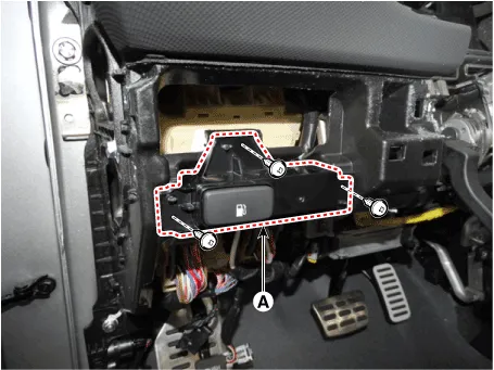
| 15. | Loosen the mounting screws and remove the A/C & heater controller unit (A).
|

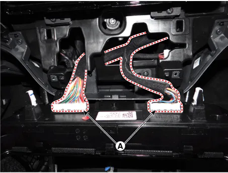
| 16. | Press the lock pin and separate the A/C & heater controller connectors (A).
|
| 17. | Loosen the mounting screws and remove the fuel panel assembly (A).
|
| 18. | Press the lock pin and separate the fuel switch connector (A).
|
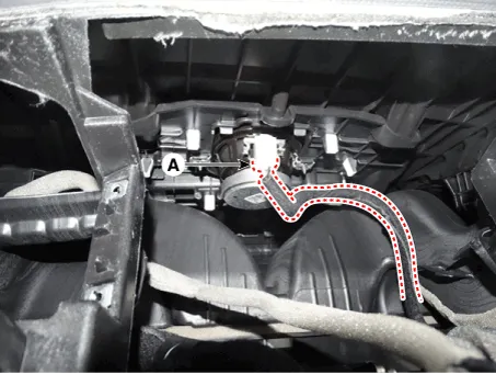
| 19. | Press the lock pin and seaprate the center speaker connector (A).
|
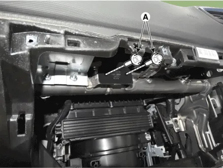
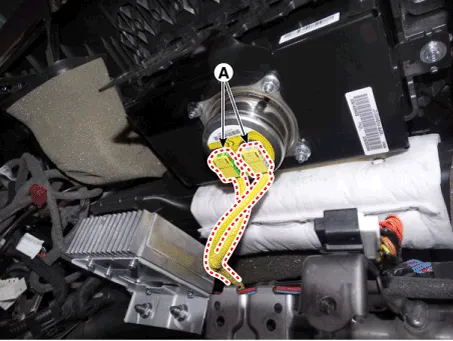
| 20. | Loosen the passenger airbag mounting bolts (A).
|
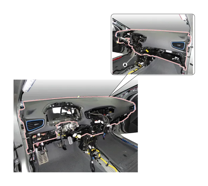
| 21. | Loosen the mounting bolts and nuts and remove the main crash pad assembly (A).
|
| 22. | Press the lock pin and separate the passenger's airbag connectors (A).
|
| 23. | To install, reverse the removal procedure.
|

Component Location 1. Main crash pad assembly
Component Location 1. Cowl cross bar assembly
Other information:
Hyundai Ioniq (AE) 2017-2022 Service & Repair Manual: Smart Cruise Control (SCC) Switch. Components and components location
C
Hyundai Ioniq (AE) 2017-2022 Service & Repair Manual: Description and operation
DescriptionRear corner radar is a system that uses two magnetic wave radar sensors attached on the rear panel to measure the distance from the following vehicles and provides the sensing and (visual and auditory) alarm of any vehicle coming into the blind spot.
Categories
- Manuals Home
- Hyundai Ioniq Owners Manual
- Hyundai Ioniq Service Manual
- Theft-alarm System
- Maintenance
- Jump starting procedure
- New on site
- Most important about car

Copyright © 2026 www.hioniqae.com - 0.0222