Hyundai Ioniq (AE): High Voltage Battery Control System / Main Relay. Repair procedures
| Removal |
|

| 1. | Shut off the high voltage. (Refer to Hybrid Control System - "High Voltage Shut-off Procedures") |
| 2. | Remove the rear seat cushion. (Refer to Body - "Rear Seat Assembly") |
| 3. | Remove the rear door scuff trim. (Refer to Body - "Door Scuff Trim") |
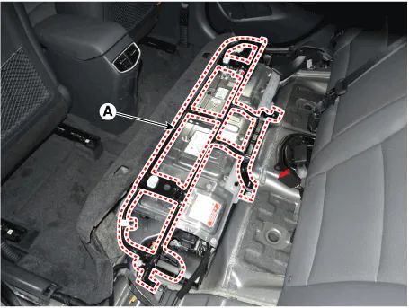
| 4. | Remove the upper frame (A) after loosening the mounting bolts and nuts.
|
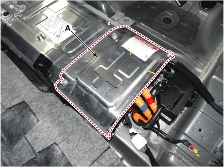
| 5. | Remove the high voltage battery rear cover (A) after loosening the mounting bolts and nuts.
|
| 6. | Remove the inlet cooling duct. (Refer to Hybrid Control System - "Cooling Duct") |
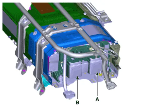
| 7. | Disconnect the main relay (+) (A), and main relay (-) (B).
|
| Installation |
|
| 1. | Install the main relay in the reverse order of removal.
|
| Inspection |
|
| [Using GDS service data to check for main relay weld damage] |
| 1. | Connect the GDS to the Data Link Connector (DLC). |
| 2. | Turn the ignition switch ON. |
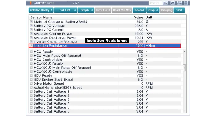
| 3. | Check the BMS weld damage state in the GDS service data.
|
| [Using a Multimeter to measure weld damage] |
| 1. | Shut off the high voltage. (Refer to Hybrid Control System - "High Voltage Shut-off Procedures") |
| 2. | Remove the high voltage battery rear cover. (Refer to High Voltage Battery System - "Case") |
| 3. | Remove the inlet cooling duct. (Refer to Hybrid Control System - "Cooling Duct") |
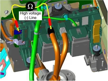
| 4. | Measure the high voltage main relay resistance and check for signs of weld damage.
|
| 1. | Shut off the high voltage. (Refer to Hybrid Control System - "High Voltage Shut-off Procedures") |
| 2. | Remove the high voltage battery rear cover. (Refer to High Voltage Battery System - "Case") |
| 3. | Remove the inlet cooling duct. (Refer to Hybrid Control System - "Cooling Duct") |
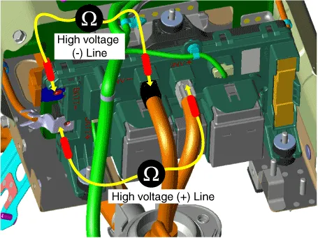
| 4. | Measure the resistance between the high voltage power terminal (-) and the inverter power terminal (-).
|
| [Circuit inspection (Relay ON)] |
|

| 1. | Connect the GDS to the Data Link Connector (DLC). |
| 2. | Turn the ignition switch ON. |
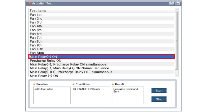
| 3. | Activate the main relay by using "Actuation Test" on the GDS as shown in the illustration below.
|
| 1. | Shut off the high voltage. (Refer to Hybrid Control System - "High Voltage Shut-off Procedures") |
| 2. | Remove the power relay assembly. (Refer to High Battery System - "Power Relay Assembly") |
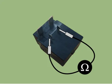
| 3. | Check for continuity between the terminals using an ohmmeter.
|
Circuit Diagram
DescriptionThe Power Relay Assembly (PRA) consists of the positive and negative main relays, pre-charge relay, pre-charge resistor and battery current sensor.
Other information:
Hyundai Ioniq (AE) 2017-2022 Service & Repair Manual: In-car Sensor. Description and operation
DescriptionThe In-car air temperature sensor is built in the heater & A/C control unit.The sensor contains a thermistor which measures the temperature of the inside. The signal decided by the resistance value which changes in accordance with perceived inside temperature, is delivered to heater control unit and according to this signal the contr
Hyundai Ioniq (AE) 2017-2022 Service & Repair Manual: Front Radar Unit. Repair procedures
Removal1.Remove the front bumper.(Refer to Body - "Front Bumper")2.Disconnect the smart cruise control unit connector (A).3.Remove the smart cruise control nuit assembly (B) from thevehicle after loosening mounting bolts.Installation1.Install in the reverse order of removal.
Categories
- Manuals Home
- Hyundai Ioniq Owners Manual
- Hyundai Ioniq Service Manual
- Repair procedures
- Jump starting procedure
- Engine Clutch System
- New on site
- Most important about car
