Hyundai Ioniq (AE): Manual Heating and Air Conditioning / Mode selection
The mode selection button controls the direction of the air flow through the ventilation system.
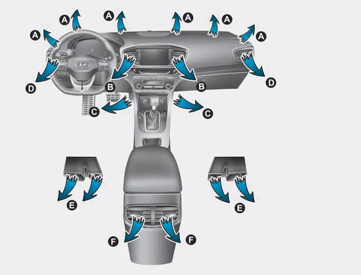
The air flow outlet direction is cycled as follows:
â– MODE DOWN ( )
)

â– MODE UP ( )
)

Face-Level (B, D, F)

Air flow is directed toward the upper body and face. Additionally, each outlet can be controlled to direct the air discharged from the outlet.
Bi-Level (B, C, D, E, F)

Air flow is directed towards the face and the floor.
Floor & Defrost (A, C, E, F)

Most of the air flow is directed to the floor and the windshield with a small amount directed to the side window defrosters.
Floor-Level (A, C, E, F)

Most of the air flow is directed to the floor, with a small amount of the air being directed to the windshield and side window defrosters.
Defrost-Level (A)
Most of the air flow is directed to the windshield with a small amount of air directed to the side window defrosters.
Interior panel vents
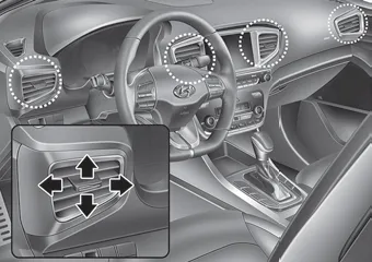
â– Front
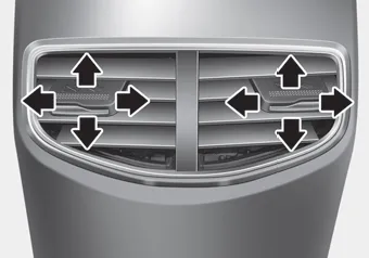
â– Rear
The outlet vents can be opened or closed ( )
using the vent control lever.
)
using the vent control lever.
Also, you can adjust the direction of air delivered from these vents using the vent control lever as shown.
The heating and cooling system can be controlled manually by pushing buttons other than the AUTO button. In this case, the system works sequentially according to the order of buttons selected.
Turn the knob to the right to increase the temperature. Turn the knob to the left to decrease temperature. The temperature will increase or decrease by 1°F/0.
Other information:
Hyundai Ioniq (AE) 2017-2022 Service & Repair Manual: Heater Unit. Components and components location
Component Location1. Heater unit assemblyCompoents1. Heater core cover2. Heater core & Seal assembly3. Mode actuator [LH]4. Temperature control actuator [LH]5. Shower duct [LH]6. Duct sensor [Floor]7. PTC Heater8. Duct sensor [Vent]9. Heater & Evaporator lower case10.
Hyundai Ioniq (AE) 2017-2022 Service & Repair Manual: Climate Control Air Filter. Repair procedures
Replacement1.Disconnect the air damper (A) from the glove box (B).2.Remove the stopper (B) from the glove box (A).3.Remove the filter cover (A) by pressing the knob.4.Replace the air filter (A) with a new one according to the direction of air filter. • To remove the filter easily, press the right side inwa
Categories
- Manuals Home
- Hyundai Ioniq Owners Manual
- Hyundai Ioniq Service Manual
- Checking the Coolant Level
- Body (Interior and Exterior)
- Theft-alarm System
- New on site
- Most important about car
