Hyundai Ioniq (AE): Lubrication System / Oil Pressure Switch. Repair procedures
Hyundai Ioniq (AE) 2017-2022 Service & Repair Manual / Engine Mechanical System / Lubrication System / Oil Pressure Switch. Repair procedures
| Removal and Installation |
| 1. | Disconnect the battery negative terminal. |
| 2. | Remove the engine room under cover. (Refer to Engine and Transaxle Assembly - "Engine Room Under Cover") |
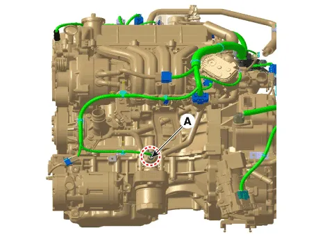
| 3. | Disconnect the oil pressure switch connector (A).
|
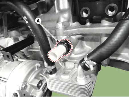
| 4. | Remove the oil pressure switch (A).
|
| 5. | Install in the reverse order of removal.
|

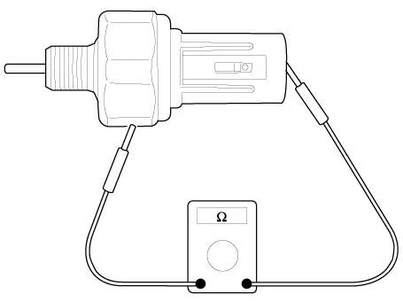
| Inspection |
| 1. | Check the continuity between the terminal and the body with an ohmmeter. If there is no continuity, replace the oil pressure switch.
|
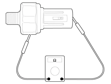
| 2. | Check the continuity between the terminal and the body when the fine wire is pushed. If there is continuity even when the fine wire is pushed, replace the switch. |
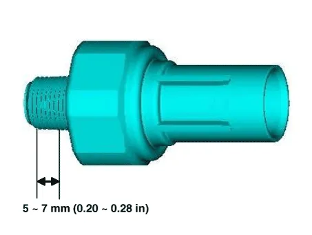
| 3. | If there is no continuity when a 50 kPa (0.50 kgf/cm², 7.25 psi) is applied through the oil hole, the switch is operaing properly. Check for air leakage. If air leaks, the diaphragm is broken. Replace it.
|
Removal and installation1.Remove the timing chain cover.(Refer to Timing System - "Timing Chain Cover")2.Remove the oil pump cover (A). Tightening torque : Screws :5.
Components1. Oil pan2. Oil screen3. Gasket4. Drain plug5. Drain plug gasket
Other information:
Hyundai Ioniq (AE) 2017-2022 Service & Repair Manual: Rear Corner Safety ON/OFF Switch. Repair procedures
Inspection1.Disconnect the negative (-) battery terminal.2.Remove the crash pad lower panel.(Refer to Body - "Crash Pad Lower Panel")3.Remove the lower crash pad switch assembly (A) after disengaging the mounting clip.4.Remove the rheostat switch connector (A).
Hyundai Ioniq (AE) 2017-2022 Service & Repair Manual: Warning Indicator. Components and components location
C
Categories
- Manuals Home
- Hyundai Ioniq Owners Manual
- Hyundai Ioniq Service Manual
- Hybrid Control System
- Heating, Ventilation and Air Conditioning
- Hybrid Vehicle Engine Compartment
- New on site
- Most important about car

Copyright © 2026 www.hioniqae.com - 0.0131