Hyundai Ioniq (AE): Lubrication System / Oil Pump. Repair procedures
| Removal and installation |
| 1. | Remove the timing chain cover. (Refer to Timing System - "Timing Chain Cover") |
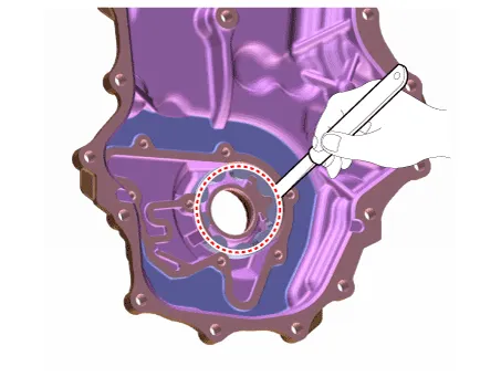
| 2. | Remove the oil pump cover (A).
|
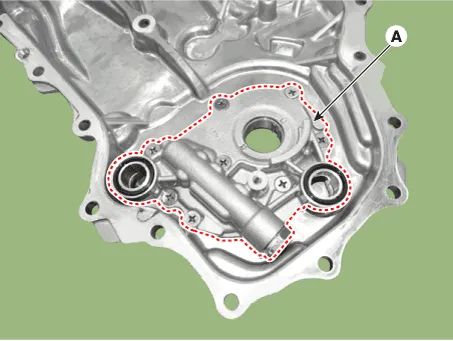
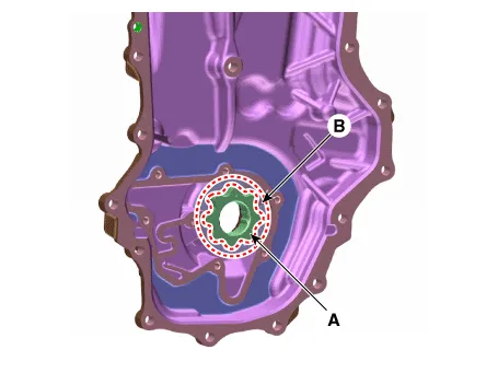
| 3. | Remove the inner rotor (A) and outer rotor (B).
|
| 4. | Install in the reverse order of removal. |
| Inspection |
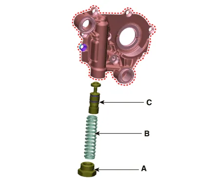
| 1. | Remove the relief plunger. Remove the plug (A), spring (B) and relief plunger (C).
|
| 2. | Inspect the relief plunger. Coat the plunger with engine oil and check that it falls smoothly into the plunger hole by its own weight. If necessary, replace timing chain cover. |
| 3. | Inspect the relief valve spring. Inspect for distortion or breakdown of the relief valve spring. |
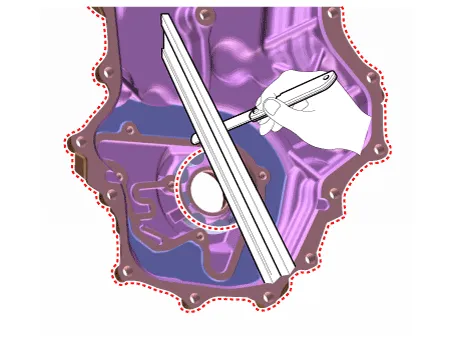
| 4. | Inspect the rotor side clearance. Using a feeler gauge and precision straight edge, measure the clearance between the inner rotors and precision straight edge. If the side clearance is greater than maximum, replace the rotors as a set. If necessary, replace the timing chain cover.
|
| 5. | Inspect the rotor body clearance. Using a feeler gauge, measure the clearance between the outer rotor and body. If the body clearance is greater than maximum, replace the rotors as a set. If necessary, replace the timing chain cover.
|
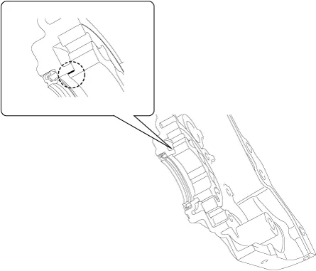
| 6. | Inspect the rotor guide clearance.
|
Components1. Inner rotor2. Outer rotor3. Oil seal4. Plug5. Relief spring6. Relief plunger7. Oil pump cover8. O-ring
Removal and Installation1.Disconnect the battery negative terminal.2.Remove the engine room under cover.(Refer to Engine and Transaxle Assembly - "Engine Room Under Cover")3.
Other information:
Hyundai Ioniq (AE) 2017-2022 Service & Repair Manual: Ambient Temperature Sensor. Repair procedures
Inspection1.Check the resistance of the ambient temperature sensor between terminals 1 and 2 whether it changes by changing the ambient temperature.1. Ambient Sensor (+)2. Sensor groundSpecification Ambient temperature [°C (°F)] Resistance between terminal 1 and 2 (
Hyundai Ioniq (AE) 2017-2022 Service & Repair Manual: Heater Core. Repair procedures
Replacement1.Disconnect the negative (-) battery terminal. 2.Remove the heater and blower assembly.(Refer to Heater - "Heater Unit") 3.Loosen the mounting screws and remove the driver's temperature control actuator (A).4.Remove the heater core cover (A) after loosening the mounting screws.
Categories
- Manuals Home
- Hyundai Ioniq Owners Manual
- Hyundai Ioniq Service Manual
- DCT(Dual Clutch Transmission) System
- Hybrid Vehicle Engine Compartment
- Checking the Coolant Level
- New on site
- Most important about car
