Hyundai Ioniq (AE): Rear Corner Radar System / Rear Corner Radar Unit. Repair procedures
Hyundai Ioniq (AE) 2017-2022 Service & Repair Manual / Advanced Driver Assistance System (ADAS) / Rear Corner Radar System / Rear Corner Radar Unit. Repair procedures
| Removal |
| 1. | Disconnect the negative (-) battery terminal. |
| 2. | Remove the rear bumper. (Refer to Body - "Rear Bumper") |
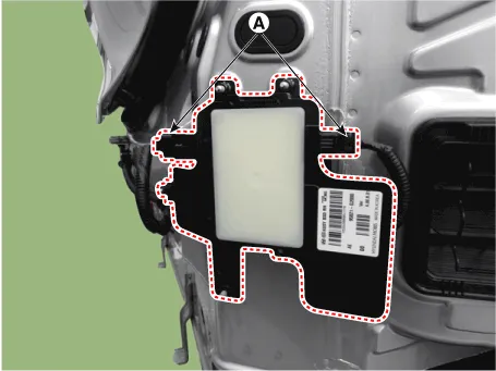
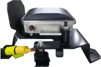
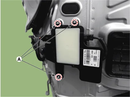
| 3. | Remove the rear corner radar unit (A) after loosening the mounting nuts.
|
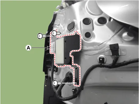

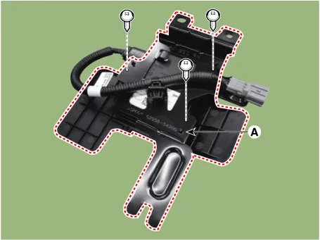
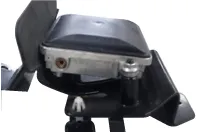
| 4. | Replace the bracket (A) when the bracket is physically changed or damaged.
|

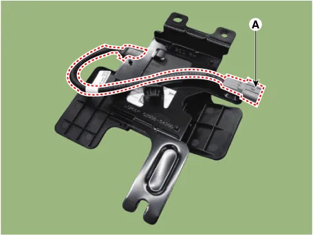
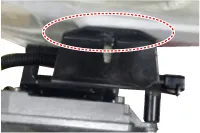
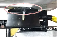
| 5. | Replace the extension wiring (A) when it damaged.
|
| Installation |
| 1. | Install the Rear corner radar unit and bracket.
|
| 2. | Install the rear bumper. |
| 3. | Connect the negative (-) battery terminal.
|
| Inspection |
Correction Overview
When you replace a rear corner radar bracket or rear corner radar components after a rear or side collision of a vehicle equipped with the rear corner radar system, you need to check if the mounting angle of the rear corner radar.
Check before Correction
| 1. | When a failure code [C2702 (Master)] or [C2703 (Slave)] occurs, check the following before performing correction. |
| 2. | Check the vehicle condition and whether the rear corner radar unit or bracket is deformed (mounting angle, twisted vehicle body, etc.).
| ||||||||||||


| 3. | Check the nut tightening. Check if there is any foreign substance.
| ||||||||||||||
Correcting the Rear Corner Radar Angle
| 1. | After replacing the rear corner radar unit or bracket, with the bumper removed, use the rear corner radar unit correction tool set (special tool : 09985-3T500) to perform angle correction.
|

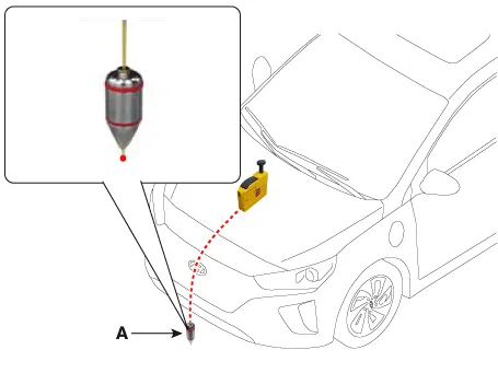
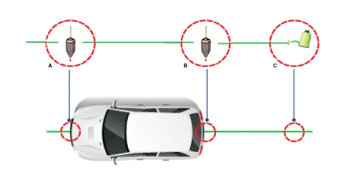
| 2. | Attach a vertical plumb (special tool : 09958-3T010) on the hood, and lower the plumb (A) to the ground so that it passes through the center of the emblem.
|
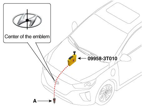
| 3. | Marking the center point below the plumb (A).
|
| 4. | Attach a vertical plumb (special tool : 09958-3T010) on the trunk (or tailgate), and lower the plumb (A) to the ground so that it passes through the center of the emblem.
|
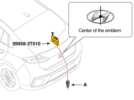
| 5. | Marking the center point below the plumb (A).
|
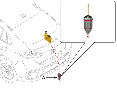
| 6. | Marking the center of vehicle by a string.
|
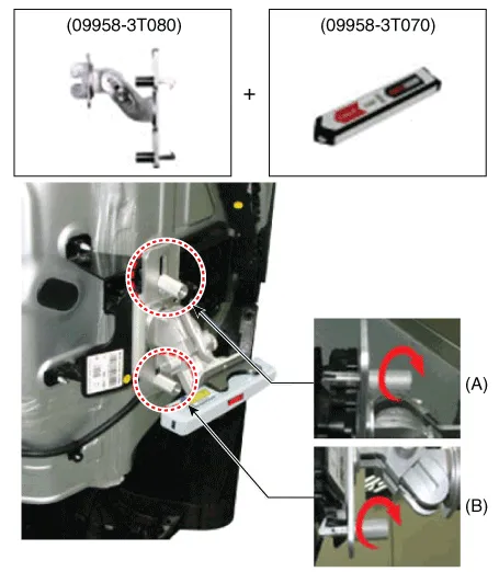
| 7. | Mount the rear corner radar unit fixing adaptor (special tool : 09958-3T080) on the rear corner radar unit and fix the level laser (special tool : 09958-3T070).
|
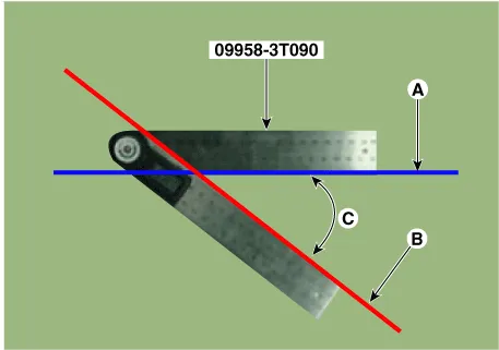
| 8. | Measure the angle (C) between the center line (A) of the angle measuring plate and the horizontal laser beam (B) using a digital protractor (special tool : 09958-3T090).
|
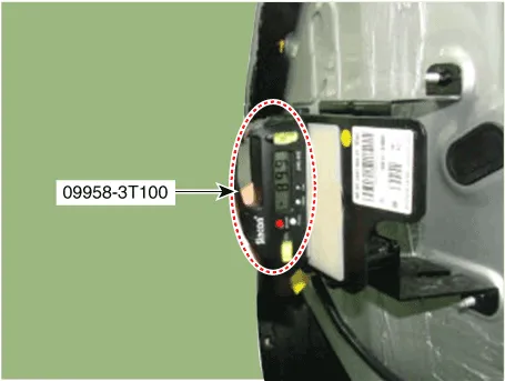
| 9. | Use a digital inclinometer (special tool : 09958-3T100) to measure the vertical angle of the rear corner radar unit.
|
| 10. | Measure the horizontal and vertical angles of left and right rear corner radar units. If the measured values deviate from the specified values, insert a washer between the bracket of the rear corner radar unit.
|
| 11. | After checking and correcting the rear corner radar unit angle, perform the rear corner radar radar correction procedure. |
rear corner radar Unit Alignment
| 1. | Rear bumper accident vehicles and vehicles that replaced rear corner radar units must perform rear corner radar unit alignment using GDS. |
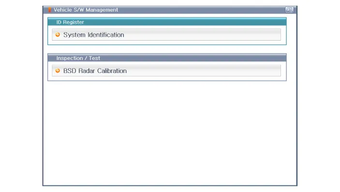
| 2. | Select "rear corner radar Radar Calibration" procedure in rear corner radar system.
|
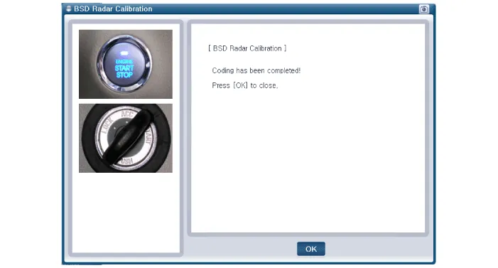
| 3. | Perform the "rear corner radar Radar Calibration" procedure according to the GDS screen message.
|
Circuit Diagram
Other information:
Hyundai Ioniq (AE) 2017-2022 Service & Repair Manual: Warning Indicator. Components and components location
C
Hyundai Ioniq (AE) 2017-2022 Service & Repair Manual: Warning Indicator. Repair procedures
RemovalWarning Indicator1.Disconnect the negative (-) battery terminal.2.Remove the mirror (A).InstallationWarning Indicator1.Install the outside mirror.2.Connect the negative (-) battery terminal.Inspection1.Apply battery voltage to each terminal as shown in the table and verify that the mirror operates properly.
Categories
- Manuals Home
- Hyundai Ioniq Owners Manual
- Hyundai Ioniq Service Manual
- Transmission Gear Oil. Repair procedures
- Jump Starting
- DCT(Dual Clutch Transmission) System
- New on site
- Most important about car

Copyright © 2026 www.hioniqae.com - 0.0141