Hyundai Ioniq (AE): Power Door Mirrors / Power Door Mirror Switch. Repair procedures
| Inspection |
| 1. | Disconnect the negative (-) battery terminal. |
| 2. | Remove the driver door trim. (Refer to Body - "Front Door Trim") |
| 3. | Disconnect the power mirror switch connector from the door trim.
|
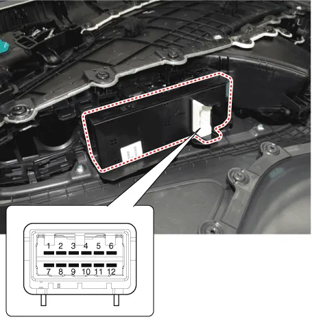
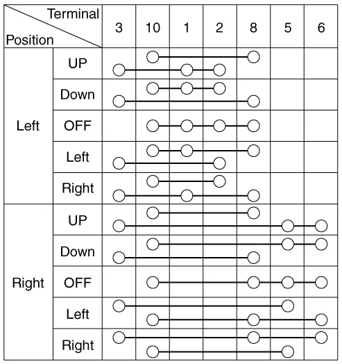
| 4. | Check for continuity between the terminals in each switch position according to the table. [Power Mirror Switch]
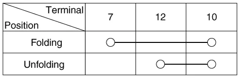
[Power Folding Mirror Switch]
|
| Removal |
| 1. | Disconnect the negative (-) battery terminal. |
| 2. | Remove the front door trim. (Refer to Body - "Front Door Trim") |
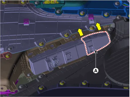
| 3. | Remove the power window assembly (A).
|
| Installation |
| 1. | Install the power window switch assembly. |
| 2. | Install the front door trim after connect the connector. |
| 3. | Connect the negative (-) battery terminal.
|

Circuit Diagram
Removal1.Disconnect (-) battery terminal.2.Using a fastener remover (C), remove the mirror (A) as illustration below. • Protect mirror from removing tool with cloth (B) wrapped.
Other information:
Hyundai Ioniq (AE) 2017-2022 Service & Repair Manual: A/C Pressure Transducer. Repair procedures
Inspection • Before measuring the pressure of the refriferant line, check whether the refrigerant amount is charged in accordance with the specified charging amount.(Refer to Heating, Ventilation, Air Conditioning - "Specifications")1.
Hyundai Ioniq (AE) 2017-2022 Service & Repair Manual: Intake Actuator. Repair procedures
Inspection1.Turn the ignition switch OFF.2.Disconnect the intake actuator connector.3.Verify that the intake actuator operates to the fresh position when connecting 12V to terminal 3 and grounding terminal 4.Verify that the intake actuator operates to the recirculation position when connected in reverse.
Categories
- Manuals Home
- Hyundai Ioniq Owners Manual
- Hyundai Ioniq Service Manual
- If the 12 Volt Battery is Discharged (Hybrid Vehicle)
- Brake System
- Body (Interior and Exterior)
- New on site
- Most important about car
