
Hyundai Ioniq (AE): High Voltage Battery System / Power Relay Assembly (PRA). Repair procedures
Hyundai Ioniq (AE) 2017-2022 Service & Repair Manual / Hybrid Control System / High Voltage Battery System / Power Relay Assembly (PRA). Repair procedures
| Removal |
|

| 1. | Shut off the high voltage. (Refer to Hybrid Control System - "High Voltage Shut-off Procedures") |
| 2. | Remove the rear seat cushion. (Refer to Body - "Rear Seat Assembly") |
| 3. | Remove the rear door scuff trim. (Refer to Body - "Door Scuff Trim") |
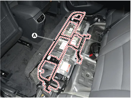
| 4. | Remove the upper frame (A) after loosening the mounting bolts and nuts.
|
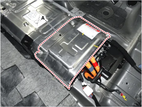
| 5. | Remove the high voltage battery rear cover (A) after loosening the mounting bolts and nuts.
|
| 6. | Remove the inlet cooling duct. (Refer to Hybrid Control System - "Cooling Duct") |
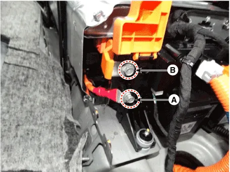
| 7. | Remove the high voltage power cable (+) terminal (A) and (-) terminal (B) after loosening the mounting bolts.
|
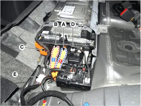
| 8. | Disconnect the inverter power connector [+] (A), inverter power connector [-] (B) and battery current sensor connector (C). |
| 9. | Disconnect the PRA connector (D, and BMS ECU extension connector (E).
|
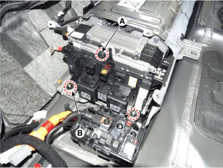
| 10. | Remove the installation bolt (A) and nut (B), then remove the power relay assembly.
|
| Installation |
|
| 1. | Install the power relay assembly in the reverse order of removal.
|
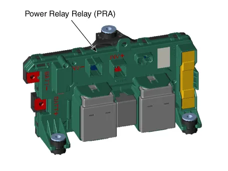
DescriptionThe Power Relay Assembly (PRA) consists of the positive and negative main relays, pre-charge relay, pre-charge resistor and battery current sensor.
Other information:
Hyundai Ioniq (AE) 2017-2022 Service & Repair Manual: emperature Control Actuator. Repair procedures
Inspection1.Turn the ignition switch OFF.2.Disconnect the temperature control actuator connector.3.Verify that the temperature control actuator operates to the cool position when connecting 12V to terminal 3 and grounding terminal 7.Verify that the temperature control actuator operates to the warm position when connected in reverse.
Hyundai Ioniq (AE) 2017-2022 Service & Repair Manual: Auto Defoging Actuator. Components and components location
C
Categories
- Manuals Home
- Hyundai Ioniq Owners Manual
- Hyundai Ioniq Service Manual
- Description and operation
- Body (Interior and Exterior)
- Maintenance
- New on site
- Most important about car

Copyright © 2026 www.hioniqae.com - 0.0203