Hyundai Ioniq (AE): High Voltage Battery Control System / Pre-Charge Resistor. Repair procedures
Hyundai Ioniq (AE) 2017-2022 Service & Repair Manual / Hybrid Control System / High Voltage Battery Control System / Pre-Charge Resistor. Repair procedures
| Removal |
| 1. | Shut off the high voltage. (Refer to Hybrid Control System - "High Voltage Shut-off Procedures") |
| 2. | Remove the rear seat cushion. (Refer to Body - "Rear Seat Assembly") |
| 3. | Remove the rear door scuff trim. (Refer to Body - "Door Scuff Trim") |
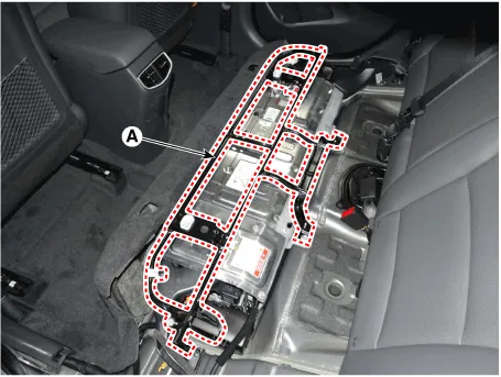
| 4. | Remove the upper frame (A) after loosening the mounting bolts and nuts.
|
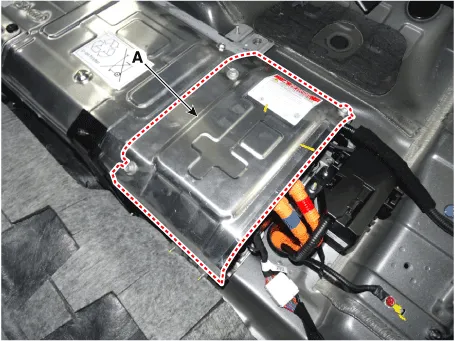
| 5. | Remove the high voltage battery rear cover (A) after loosening the mounting bolts and nuts.
|
| 6. | Remove the inlet cooling duct. (Refer to Hybrid Control System - "Cooling Duct") |
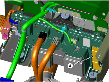
| 7. | Disconnect the pre-charge resistor (A).
|

| Installation |
|

| 1. | Install in the reverse order of removal.
|
| Inspection |
| 1. | Remove the pre-charge resistor. (Refer to High Voltage Battery Control System - "Pre-Charge Resistor") |
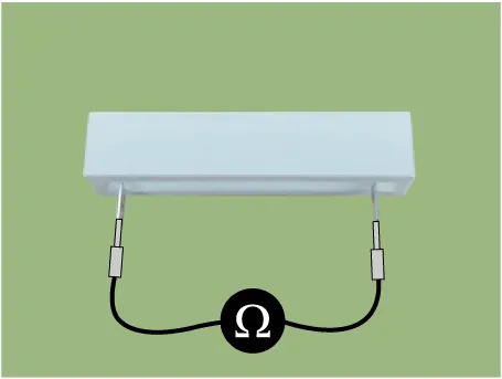
| 2. | Check for continuity between the terminals using an ohmmeter.
|
Circuit Diagram
DescriptionBattery Current Sensor is integrated into the Power Relay Assembly (PRA) and measures the current of the high voltage battery during charging or discharging.
Other information:
Hyundai Ioniq (AE) 2017-2022 Service & Repair Manual: Rear Corner Safety ON/OFF Switch. Repair procedures
Inspection1.Disconnect the negative (-) battery terminal.2.Remove the crash pad lower panel.(Refer to Body - "Crash Pad Lower Panel")3.Remove the lower crash pad switch assembly (A) after disengaging the mounting clip.4.Remove the rheostat switch connector (A).
Hyundai Ioniq (AE) 2017-2022 Service & Repair Manual: Schematic diagrams
System Block DiagramComponent Parts and Function Outline Component part Function Vehicle-speed sensor, ESP/ABS Control ModuleConverts vehicle speed to pulse.VCUReceives signals from sensor and control switches.
Categories
- Manuals Home
- Hyundai Ioniq Owners Manual
- Hyundai Ioniq Service Manual
- Engine Control/Fuel System
- General Information
- DCT(Dual Clutch Transmission) System
- New on site
- Most important about car

Copyright © 2026 www.hioniqae.com - 0.0217