Hyundai Ioniq (AE): Rear Suspension System / Rear Shock Absorber. Repair procedures
Hyundai Ioniq (AE) 2017-2022 Service & Repair Manual / Suspension System / Rear Suspension System / Rear Shock Absorber. Repair procedures
| Removal |
| 1. | Loosen the wheel nuts slightly. Raise the vehicle, and make sure it is securely supported. |
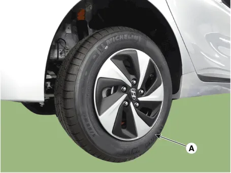
| 2. | Remove the rear wheel and tire (A) from the rear hub.
|

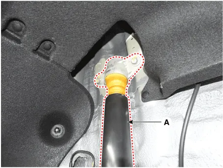
| 3. | Remove the rear shock absorber (A) from the frame by loosening the bolt.
|
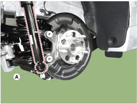
| 4. | Loosen the bolt & nut and then remove the rear shock absorber (A) from the torsion beam axle.
|
| 5. | Install in the reverse order of removal. |
| Disassembly |
| 1. | Remove the lock nut cover (A).
|
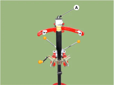
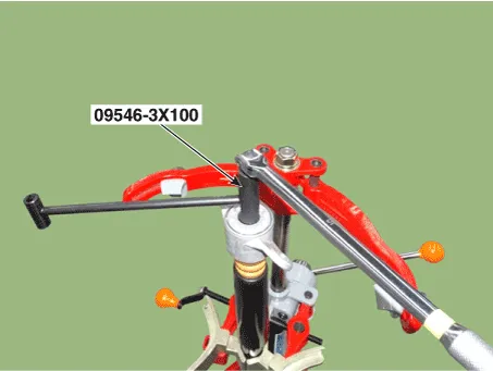
| 2. | Using the special tool (09546-3X100), install the self locking nut.
|
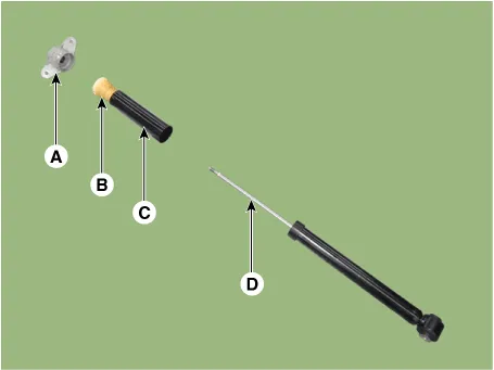
| 3. | Separate the bracket assembly (A), bumper rubber (B), dust cover (C), shock absorber (D).
|
| Disposal |
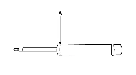
| 1. | Remove the strike cap (A) from the shock absorber assembly. |
| 2. | Remove the gas by Drilling a hole in the inner oil seal.
|

| Reassembly |
| 1. | To reassembly, reverse the disassembly procedure. |
| 2. | Using SST (09546-3X100), install the lock nut.
|
| 3. | Install the lock nut cover (A).
|
Components1. Shock absorber dust cap2. Lock nut3. Insulator assembly 4. Bumper rubber5. Dust cover6. Shock absorber
Removal1.Loosen the wheel nuts slightly.Raise the vehicle, and make sure it is securely supported.2.Remove the rear wheel and tire (A) from the rear hub.
Categories
- Manuals Home
- Hyundai Ioniq Owners Manual
- Hyundai Ioniq Service Manual
- Suspension System
- If the 12 Volt Battery is Discharged (Hybrid Vehicle)
- Hybrid Control System
- New on site
- Most important about car

Copyright © 2026 www.hioniqae.com - 0.0083