Hyundai Ioniq (AE): Manifold Absolute Pressure Sensor (MAPS) / Repair procedures
| Inspection |
| 1. | Connect the GDS on the Data Link Connector (DLC). |
| 2. | Measure the output voltage of the MAPS at idle and IG ON.
|
| Removal |
| 1. | Turn ignition switch OFF and disconnect the negative (-) battery cable. |
| 2. | Remove the air cleaner assembly (Refer to Engine Mechanical System - "Air Cleaner") |
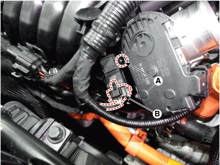
| 3. | Disconnect the manifold absolute pressure sensor connector (A). |
| 4. | Remove the installation bolt (B), and then remove the sensor from the surge tank.
|
| Installation |
|

|
| 1. | Install in the reverse order of removal.
|
Circuit Diagram
DescriptionMAFS uses a hot-film type sensing element to measure the mass of intake air entering the engine, and send the signal to ECM.A large amount of intake air represents acceleration or high load conditions while a small amount of intake air represents deceleration or idle.
Other information:
Hyundai Ioniq (AE) 2017-2022 Service & Repair Manual: A/C Pressure Transducer. Description and operation
DescriptionThe A/C Pressure Transducer (APT) converts the pressure value of high pressure line into voltage value after measuring it. By converted voltage value, engine ECU controls the cooling fan by operating it high speed or low speed. Engine ECU stops the operation of the compressor when the temperature of refrigerant line is very high or very
Hyundai Ioniq (AE) 2017-2022 Service & Repair Manual: Repair procedures
Self Diagnosis1.Self-diagnosis process. • When operating the self-diagnostics, the below fault (self-diagnostics code) will blink at 0.5 seconds interval on the temperature display settings (driver's side only) and the remaining symbols are OFF .
Categories
- Manuals Home
- Hyundai Ioniq Owners Manual
- Hyundai Ioniq Service Manual
- Brake System
- Hybrid Vehicle Engine Compartment
- If the 12 Volt Battery is Discharged (Hybrid Vehicle)
- New on site
- Most important about car
