Hyundai Ioniq (AE): Manifold Absolute Pressure Sensor (MAPS) / Schematic diagrams
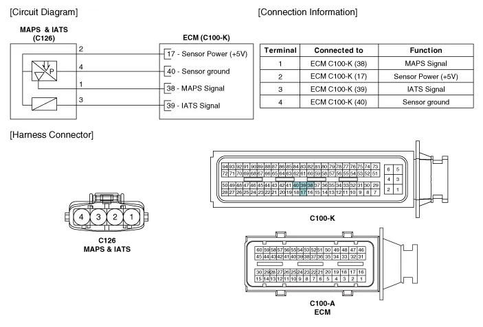
| Circuit Diagram |
Signal Waveform
Inspection1.Connect the GDS on the Data Link Connector (DLC).2.Measure the output voltage of the MAPS at idle and IG ON. Specification : Refer to "Specification"Removal 1.
Other information:
Hyundai Ioniq (AE) 2017-2022 Service & Repair Manual: Mode Control Actuator. Specifications
S
Hyundai Ioniq (AE) 2017-2022 Service & Repair Manual: Blower Motor. Repair procedures
Inspection1.Connect the battery voltage and check the blower motor rotation.2.If the blower motor does not operate well, substitute with a known-good blower motor and check for proper operation.3.Replace the blower motor if it is proved that there is a problem with it.
Categories
- Manuals Home
- Hyundai Ioniq Owners Manual
- Hyundai Ioniq Service Manual
- Body (Interior and Exterior)
- Jump Starting
- Transmission Gear Oil. Repair procedures
- New on site
- Most important about car

Copyright © 2026 www.hioniqae.com - 0.0151