Hyundai Ioniq (AE): Heated Steering wheel / Repair procedures
| Removal |
| 1. | Disconnect the negative (-) battery terminal. |
| 2. | Remove the glove box. (Refer to Body - "Glove Box Upper Cover Assembly") |
| 3. | Remove the smart key unit. (Refer to Body - "Smart Key Unit") |
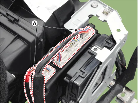
| 4. | Disconnect the body control module connectors (A).
|
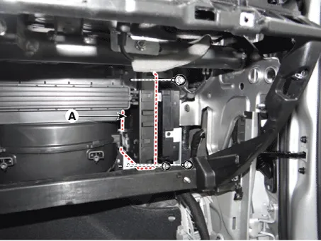
| 5. | Remove the body control module (A) after loosening the mounting nuts.
|
| 6. | Install in the reverse order of removal. |
| Heated steering wheel switch |
| 1. | Disconnect the negative (-) battery terminal. |
| 2. | Remove the floor console upper complete assembly. (Refer to Body - "Floor Console Assembly") |
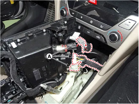
| 3. | Disconnect the connector (A).
|
| 4. | Install in the reverse order of removal. |
| Inpection |
| 1. | Measure a resistance of NTC and Heated pad.
|
| 2. | Measure a temperature.
|
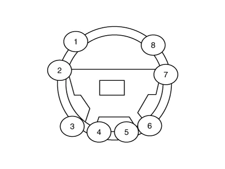
System Circuit DiagramBody control ModuleHeated steering switchHeated steering padTermainal functionBody control module Pin Function D3Ignition 2_Heated handle powerD4Ignition 2_Heated handle power_2D5Heated handleC22NTC (-)C9NTC (+)C4Heated handle switchHeated steering wheel pad Housing Pin Function Wire color PadAGroundBLACKBHEATERYELLOWCNTC+GRAYDNTC-BLACKHeated steering wheel switch Pin Function 7Wheel heated12Wheel heated IND.
Other information:
Hyundai Ioniq (AE) 2017-2022 Service & Repair Manual: Blower Unit. Components and components location
Component Location1. Blower unit assembly Components1. Duct Seal2. Intake duct case3. Air intake door assembly4. Intake door5. Seal6. Intake duct case (A)7. Air filter cover (A)8. Intake actuator9. Air filter cover10. Air filter 11. Blower unit pad12.
Hyundai Ioniq (AE) 2017-2022 Service & Repair Manual: Intake Actuator. Specifications
S
Categories
- Manuals Home
- Hyundai Ioniq Owners Manual
- Hyundai Ioniq Service Manual
- Brake System
- Heating, Ventilation and Air Conditioning
- Repair procedures
- New on site
- Most important about car
