Hyundai Ioniq (AE): Heated Steering wheel / Schematic diagrams
Hyundai Ioniq (AE) 2017-2022 Service & Repair Manual / Steering System / Steering wheel / Heated Steering wheel / Schematic diagrams
| System Circuit Diagram |
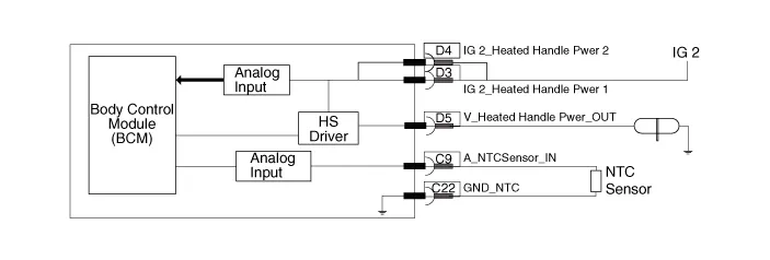
| Body control Module |
| Heated steering switch |
| Heated steering pad |
| Termainal function |
| Body control module |
|
Pin
|
Function
|
| D3 | Ignition 2_Heated handle power |
| D4 | Ignition 2_Heated handle power_2 |
| D5 | Heated handle |
| C22 | NTC (-) |
| C9 | NTC (+) |
| C4 | Heated handle switch |
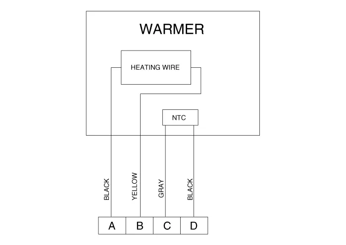
| Heated steering wheel pad |

|
Housing
|
Pin
|
Function
|
Wire color
|
| Pad | A | Ground | BLACK |
| B | HEATER | YELLOW | |
| C | NTC+ | GRAY | |
| D | NTC- | BLACK |
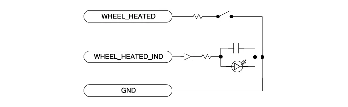
| Heated steering wheel switch |

|
Pin
|
Function
|
| 7 | Wheel heated |
| 12 | Wheel heated IND. |
| 1 | Ground |
Specifications Item Specification Voltage13.5 VHeated pad resistance1.8 Ω ± 0.2 Ω NTC resistance10.
Removal1.Disconnect the negative (-) battery terminal.2.Remove the glove box.(Refer to Body - "Glove Box Upper Cover Assembly")3.Remove the smart key unit.
Other information:
Hyundai Ioniq (AE) 2017-2022 Service & Repair Manual: Smart Cruise Control (SCC) Switch. Repair procedures
Removal1.Disconnect the negative (-) battery terminal.2.Remove the steering wheel assembly.(Refer to Steering System -"Steering Wheel")3.Remove the steering back cover (A).4.Remove the steering remote control connector (A).5.Remove the steering remote control (A), after loosening the screws.
Hyundai Ioniq (AE) 2017-2022 Service & Repair Manual: Warning Indicator. Components and components location
C
Categories
- Manuals Home
- Hyundai Ioniq Owners Manual
- Hyundai Ioniq Service Manual
- Brake System
- Repair procedures
- Transmission Gear Oil. Repair procedures
- New on site
- Most important about car

Copyright © 2026 www.hioniqae.com - 0.0151