Hyundai Ioniq (AE): Seat Belt Pretensioner. Seat Belt Pretensioner (BPT) / Repair procedures
| Removal |
[Front Seat Belt Pretensioner]
| 1. | Disconnect the battery negative cable, and wait for at least three minutes before beginning work. |
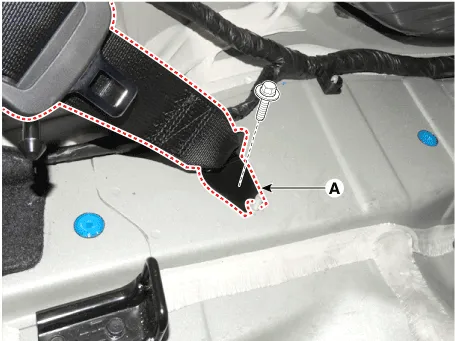
| 2. | Separate the front seat belt (A) from the emergency fastening device.
|
| 3. | Remove the door scuff trim. (Refer to Body - "Interior Trim") |
| 4. | Remove the center pillar trim. (Refer to Body - "Interior Trim") |
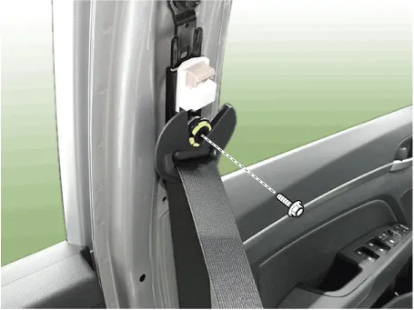
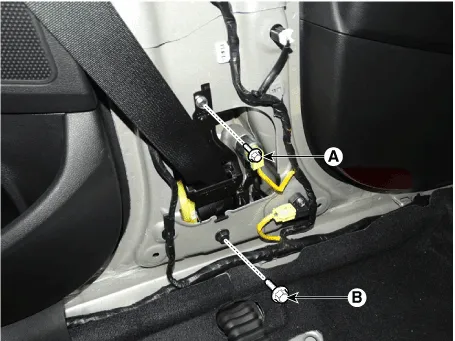
| 5. | Remove the front seat belt upper anchor bolt.
|
| 6. | Disconnect the front seat belt pretensioner connector (A).
|
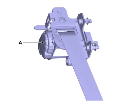
| 7. | Remove the seat belt pretensioner (A) after loosening the seat belt pretensioner mounting bolts.
|
[Rear Seat Belt Pretensioner]
| 1. | Disconnect the battery negative cable and wait for at least 3 minutes before beginning work.
|

| 2. | Remove the rear pillar trim. (Refer to Body - "Rear Pillar Trim") |
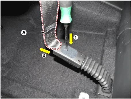
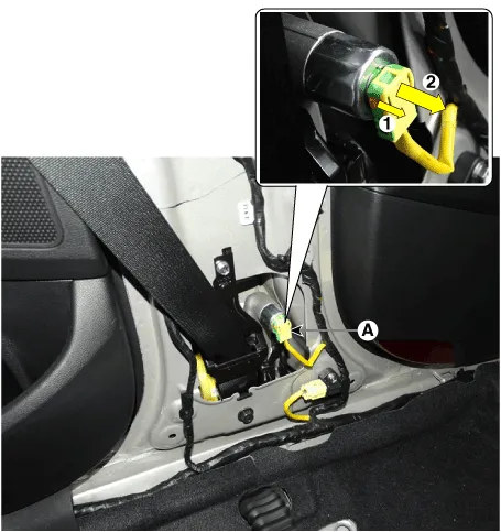
| 3. | Remove the rear seat belt lower anchor bolt (A).
|
| 4. | Disconnect the pretensioner connector. |
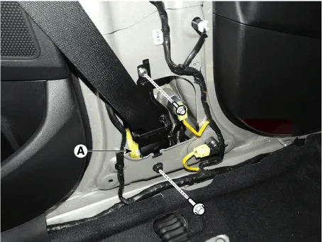
| 5. | Remove the rear seat belt pretensioner (A) after loosening mounting bolts.
|
| Installation |
[Front Seat Belt Pretensioner]
| 1. | Remove the ignition key from the vehicle. |
| 2. | Disconnect the battery negative cable and wait for at least three minutes. |
| 3. | Install the seat belt pretensioner.
|
| 4. | Connect the seat belt pretensioner connector.
|
| 5. | Install the front seat belt upper anchor bolt.
|
| 6. | Install the center pillar trim. (Refer to Body - "Interior Trim") |
| 7. | Install the door scuff trim. (Refer to Body - "Interior Trim") |
| 8. | Reconnect the battery negative cable. |
| 9. | After installing the seat belt pretensioner, confirm proper system operation:
|
[Rear Seat Belt Pretensioner]
| 1. | Disconnect the battery neg ative cable and wait for at least 3 minutes before beginning work.
|
| 2. | Install the rear seat belt pretensioner.
|
| 3. | Install the rear seat belt lower anchor bolt.
|
| 4. | Install the rear pillar trim. (Refer to Body - "Rear Pillar Trim") |
| 5. | Reconnect the battery negative cable. |
| 6. | After installing the seat belt pretensioner, confirm proper system operation:
|
Components 1. Front Seat Belt Pretensioner 2. Rear Seat Belt Pretensioner
Other information:
Hyundai Ioniq (AE) 2017-2022 Service & Repair Manual: Blower Motor. Repair procedures
Inspection1.Connect the battery voltage and check the blower motor rotation.2.If the blower motor does not operate well, substitute with a known-good blower motor and check for proper operation.3.Replace the blower motor if it is proved that there is a problem with it.
Hyundai Ioniq (AE) 2017-2022 Service & Repair Manual: Description and operation
Cruise ControlThe cruise control system is engaged by the cruise "ON/OFF" main switch located on right of steering wheel column. The system has the capability to cruise, coast, accelerate and resume speed.It also has a safety interrupt, engaged upon depressing brake or shifting select lever.
Categories
- Manuals Home
- Hyundai Ioniq Owners Manual
- Hyundai Ioniq Service Manual
- Maintenance
- Jump Starting
- Checking the Coolant Level
- New on site
- Most important about car

Copyright © 2026 www.hioniqae.com - 0.0129