Hyundai Ioniq (AE): Autonomous Emergency Braking(AEB) System / Schematic diagrams
Hyundai Ioniq (AE) 2017-2022 Service & Repair Manual / Brake System / Autonomous Emergency Braking(AEB) System / Schematic diagrams
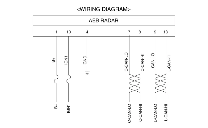
| Schematic Diagram |
| Terminal Function |

|
No
|
Terminal function
|
| 1 | B+ |
| 2 | NC |
| 3 | NC |
| 4 | GND |
| 5 | NC |
| 6 | NC |
| 7 | C-CAN_Low |
| 8 | C-CAN_High |
| 9 | L-CAN_Low |
| 10 | IGN1 |
| 11 | NC |
| 12 | NC |
| 13 | NC |
| 14 | NC |
| 15 | NC |
| 16 | NC |
| 17 | NC |
| 18 | L-CAN_High |
ComponentsThe following is the configuration of the AEB system.– Detection device (radar and camera) that can recognize potential obstacles in the front.
InspectionAEB function ON / OFF switch was included to USM (User Setting Menu) and the state of the factory is ON.When the IGN On, maintain ON condition by default.
Categories
- Manuals Home
- Hyundai Ioniq Owners Manual
- Hyundai Ioniq Service Manual
- DCT(Dual Clutch Transmission) System
- Engine Mechanical System
- Suspension System
- New on site
- Most important about car

Copyright © 2026 www.hioniqae.com - 0.0172