Hyundai Ioniq (AE): Autonomous Emergency Braking(AEB) System / Components and components location
Hyundai Ioniq (AE) 2017-2022 Service & Repair Manual / Brake System / Autonomous Emergency Braking(AEB) System / Components and components location
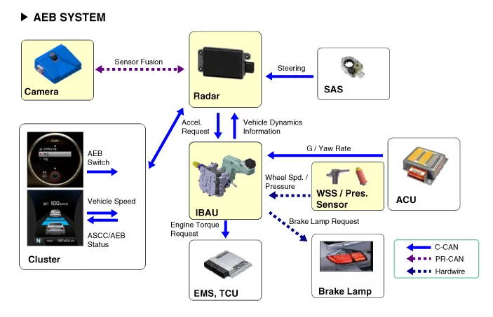
| Components |
The following is the configuration of the AEB system.
| – | Detection device (radar and camera) that can recognize potential obstacles in the front. |
| – | Human-Machine Interface (HMI) to warn driver or change settings. |
| – | Braking system to automatically brake the car |
AEB, contrary to SCC (Smart Cruise Control), has to work on a stationary car so the system uses the Fusion Target system to combine radar with camera.
Description– AEB system is designed to help avoid a potential collision or reduce its impact when drivers applies inadequate, delayed or no brakes at all to avoid a collision.
Schematic DiagramTerminal Function No Terminal function 1B+2NC3NC4GND5NC6NC7C-CAN_Low8C-CAN_High9L-CAN_Low10IGN111NC12NC13NC14NC15NC16NC17NC18L-CAN_High
Categories
- Manuals Home
- Hyundai Ioniq Owners Manual
- Hyundai Ioniq Service Manual
- Repair procedures
- Brake System
- If the 12 Volt Battery is Discharged (Hybrid Vehicle)
- New on site
- Most important about car

Copyright © 2026 www.hioniqae.com - 0.0114