Hyundai Ioniq (AE): High Voltage Battery Control System / Specifications
| Specification |
|
Item
|
Specification
| |
| Rated Voltage (V) | 400 | |
| Rated Current (A) | 80 | |
| Fuse Rated Current (A) | 125 | |
| Fuse Melting Time | Rated Current x 110% | Min. 4 hr |
| Rated Current x 200% | 5 - 100 sec | |
| Rated Current x 300% | 0.5 - 15 sec | |
| Rated Current x 500% | Max. 1 sec | |
|
Item
|
Specification
| |
| Contact | Rated Voltage (V) | 450 |
| Rated Current (A) | 80 | |
| Coil | Operating Voltage (V) | 12 |
| Resistance (Ω) | 20.0 - 40.0 [20°C (68°F)] | |
|
Item
|
Specification
| |
| Contact | Rated Voltage (V) | 450 |
| Rated Current (A) | 20 | |
| Coil | Operating Voltage (V) | 12 |
| Resistance (Ω) | 40.0 - 110.0 [20°C (68°F)] | |
|
Item
|
Specification
|
| Resistance (Ω) | 40 [20°C (68°F)] |
| Rated Current (A) | 40 |
|
Current (A)
|
Output Voltage (V)
|
| -300 (Charge) | 0.5 |
| 0 | 2.5 |
| +300 (Discharge) | 4.5 |
|
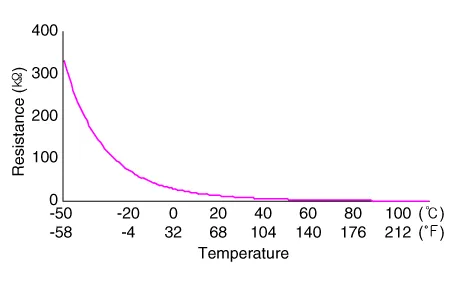
Temperature
|
Resistance (kΩ)
| |
|
°C
|
°F
| |
| -50 | -58 | 314.9 - 344.6 |
| -40 | -40 | 181.1 - 196.0 |
| -30 | -22 | 107.5 - 115.2 |
| -20 | -4 | 65.82 - 69.77 |
| -10 | 14 | 41.43 - 43.52 |
| 0 | 32 | 26.74 - 27.83 |
| 10 | 50 | 17.67 - 18.25 |
| 20 | 68 | 11.94 - 12.24 |
| 30 | 86 | 8.214 - 8.411 |
| 40 | 104 | 5.738 - 5.918 |
| 50 | 122 | 4.082 - 4.239 |
| 60 | 140 | 2.954 - 3.087 |
| 70 | 158 | 2.172 - 2.284 |
| 80 | 176 | 1.621 - 1.715 |
| 90 | 194 | 1.227 - 1.305 |
| 100 | 212 | 0.941 - 1.006 |
| 110 | 230 | 0.731 - 0.785 |
|
Temperature
|
Resistance (kΩ)
| |
|
°C
|
°F
| |
| -50 | -58 | 351.1 - 385.0 |
| -40 | -40 | 196.6 - 213.1 |
| -30 | -22 | 114.4 - 122.7 |
| -20 | -4 | 68.94 - 73.15 |
| -10 | 14 | 42.59 - 44.76 |
| 0 | 32 | 27.14 - 28.27 |
| 10 | 50 | 17.78 - 18.36 |
| 20 | 68 | 11.96 - 12.25 |
| 30 | 86 | 8.202 - 8.399 |
| 40 | 104 | 5.721 - 5.901 |
| 50 | 122 | 4.069 - 4.226 |
| 60 | 140 | 2.945 - 3.078 |
| 70 | 158 | 2.169 - 2.280 |
| 80 | 176 | 1.622 - 1.715 |
| 90 | 194 | 1.228 - 1.306 |
DescriptionThe high voltage battery system consists of the BMS ECU (Battery Management System ECU), Power Relay Assembly (PRA), safety plug, battery temperature sensor, and battery ambient sensor.
Component Location1. BMS ECU2. Power Relay Assembly (PRA)3. Safety Plug4. Battery Temperature Sensor5. Battery Ambient Sensor • Main Relays (Positive, Negative), Pre-Charge Relay, Pre-Charge Resistor, and Battery Current Sensor are integrated into the PRA.
Other information:
Hyundai Ioniq (AE) 2017-2022 Service & Repair Manual: Duct Sensor. Repair procedures
Inspection1.Check that the voltage values of No. 1, 2 duct sensors change1. Sensor (+ 5V)2. Sensor groundSpecification Ambient temperature [°C (°F)] Resistance (kΩ) Voltage (V) 50 (122)1.
Hyundai Ioniq (AE) 2017-2022 Service & Repair Manual: Components and components location
C
Categories
- Manuals Home
- Hyundai Ioniq Owners Manual
- Hyundai Ioniq Service Manual
- Checking the Coolant Level
- Repair procedures
- Maintenance
- New on site
- Most important about car
