Hyundai Ioniq (AE): SRSCM / SRS Control Module (SRSCM). Repair procedures
| Removal |
| 1. | Remove the ignition key from the vehicle. |
| 2. | Disconnect the battery negative cable and wait for at least three minutes before beginning work. |
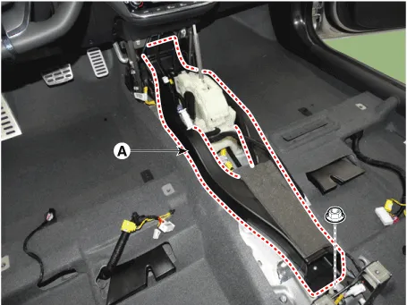
| 3. | Remove the floor console. (Refer to Body - "Floor Console Assembly") |
| 4. | Remove the center console duct (A) after loosening the mounting nut.
|
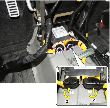
| 5. | Disconnect the SRSCM connectors.
|
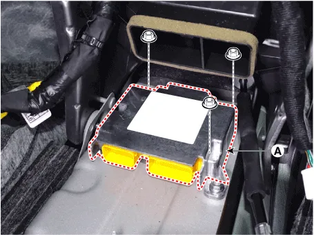
| 6. | Remove the SRSCM (A) after loosening the mounting nuts.
|
| Installation |
| 1. | Remove the ignition key from the vehicle. |
| 2. | Disconnect the battery negative cable and wait for at least three minutes before beginning work. |
| 3. | Install the SRSCM (A) with the SRSCM mounting nuts.
|
| 4. | Connect the SRSCM harness connectors. |
| 5. | Install the heater ducts and floor console. (Refer to Body - "Floor Console Assembly") |
| 6. | Reconnect the battery negative cable. |
| 7. | After installing the SRSCM, confirm proper system operation : Turn the ignition switch ON; the SRS indicator light should be turned on for about six seconds and then go off.
|

| Variant Coding |
|

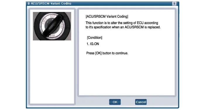
| â– On-line Type on GDS |
| 1. | Turn the ignition switch OFF. |
| 2. | Connect the GDS. |
| 3. | Turn the ignition switch ON without the engine running. |
| 4. | Select vehicle name and airbag system. |
| 5. | Select variant coding mode. |
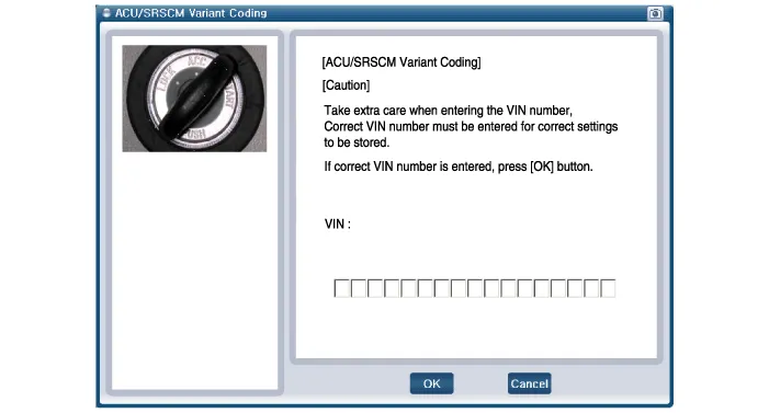
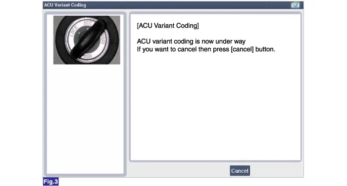
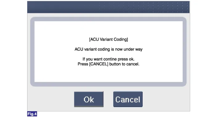
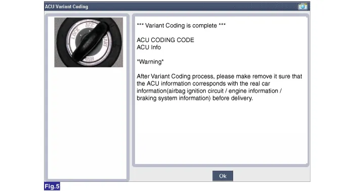
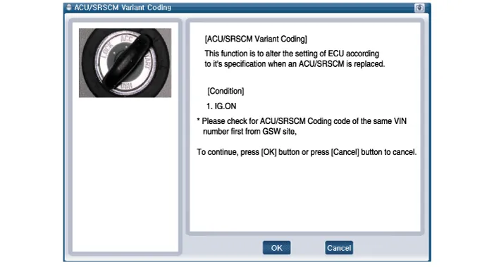
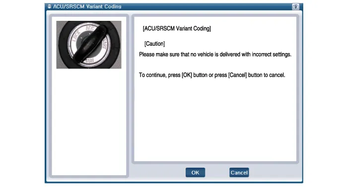
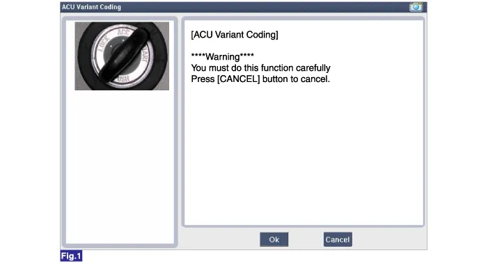
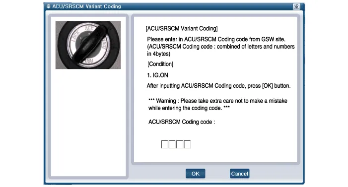
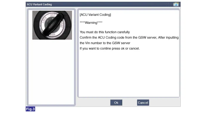
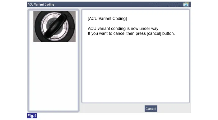
| 6. | Follow the steps on the screen below.
|
|
| â– OFF-Line Type on GDS (Use When Not Connected to the Internet) |
| 1. | Turn the ignition switch OFF. |
| 2. | Connect the GDS. |
| 3. | Turn the ignition switch ON without the engine running. |
| 4. | Select vehicle name and airbag system. |
| 5. | Select variant coding mode. |
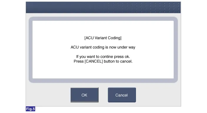
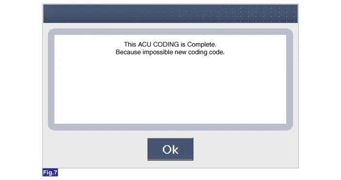
| 6. | Follow the steps on the screen below.
|
Components1. Supplemental Restraint System Control Module (SRSCM)Supplemental Restraint System Control Module (SRSCM) No Connector A Connector B 1IGN 1Ground2Driver front impact sensor - High (+)Driver seat belt pretensioner - High (+)3Driver front impact sensor - Low (-)Driver seat belt pretensioner - Low (-)4Driver airbag 1st stage - High (+)-5Driver airbag 1st stage - Low (-)-6Passenger airbag 1st stage - Low (-)Driver side airbag - High (+)7Passenger airbag 1st stage - High (+)Driver side airbag - Low (-)8Passenger airbag ON/OFF switch - Low (-)Passenger side airbag - Low (-)9Passenger airbag ON/OFF switch - High (+)Passenger side airbag - High (+)10Crash signal outputDriver side impact sensor - High (+)11Passenger front impact sensor - High (+)Driver side impact sensor - Low (-)12Passenger front impact sensor - Low (-)Passenger side impact sensor - Low (-)13-Passenger side impact sensor - High (+)14--15-Passenger seat belt pretensioner - High (+)16-Passenger seat belt pretensioner - Low (-)17P-CAN (High)-18P-CAN (Low)-19-Driver curtain airbag - High (+)20PAB OFF LampDriver curtain airbag - Low (-)21PAB ON LampPassenger curtain airbag - Low (-)22Driver Knee Airbag - High (+)Passenger curtain airbag - High (+)23Driver Knee Airbag - Low (-)Driver Passenger side impact sensor - High (+)24-Driver pressure side impact sensor - Low (-)25-Passenger pressure side impact sensor - Low (-)26C-CAN (High)Passenger Passenger side impact sensor - High (+)27C-CAN (Low)-28-29-30-31-32-33-34-35-36-37-38-39-
Description• The front impact sensors (FIS) are installed on the upper of the side panel in Front End Module (FEM). They are remote sensors that detect acceleration due to a collision at their mounting locations.
Other information:
Hyundai Ioniq (AE) 2017-2022 Service & Repair Manual: Duct Sensor. Repair procedures
Inspection1.Check that the voltage values of No. 1, 2 duct sensors change1. Sensor (+ 5V)2. Sensor groundSpecification Ambient temperature [°C (°F)] Resistance (kΩ) Voltage (V) 50 (122)1.
Hyundai Ioniq (AE) 2017-2022 Service & Repair Manual: Specifications
S
Categories
- Manuals Home
- Hyundai Ioniq Owners Manual
- Hyundai Ioniq Service Manual
- Maintenance
- Hybrid Control System
- Suspension System
- New on site
- Most important about car
