Hyundai Ioniq (AE): Timing System / Timing Chain. Repair procedures
Hyundai Ioniq (AE) 2017-2022 Service & Repair Manual / Engine Mechanical System / Timing System / Timing Chain. Repair procedures
| Removal |
|

| 1. | Shut off the high voltage circuit. (Refer to General Information - "High Voltage Shutoff Procedure") |
| 2. | Disconnect the battery negative terminal. |
| 3. | Remove the cylinder head cover. (Refer to Cylinder Head Assembly - "Cylinder Head Cover") |
| 4. | Set No.1 cylinder to TDC (Top dead center) on compression stroke.
|
| 5. | Remove the timing chain cover. (Refer to Timing System - "Timing Chain Cover") |
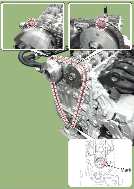
| 6. | Put paint marks on the timing chain links (3 places) that meet with the timing marks of the camshaft sprockets (In, Ex : 2) and the crankshaft sprocket. |
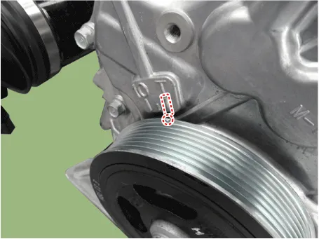
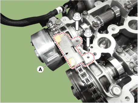
| 7. | Remove the timing chain tensioner (A).
|


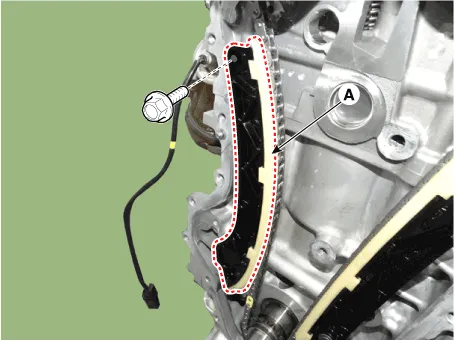
| 8. | Remove the timing chain tensioner arm (A).
|
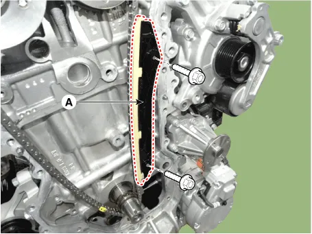
| 9. | Remove the timing chain guide (A).
|
| 10. | Remove the timing chain cam guide (A).
|
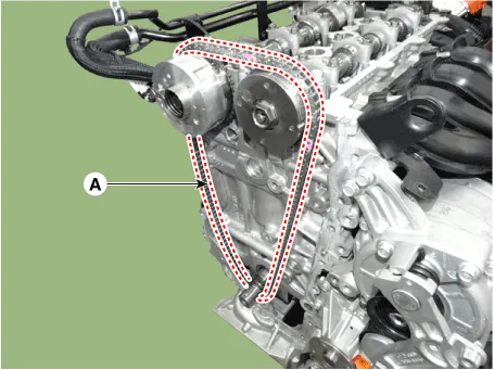
| 11. | Remove the timing chain (A).
|
| Inspection |
Sprockets, Chain Tensioner, Chain Guide, Chain Tensioner Arm
| 1. | Check the camshaft sprocket and crankshaft sprocket for abnormal wear, cracks, or damage. Replace as necessary. |
| 2. | Inspect the tensioner arm and chain guide for abnormal wear, cracks, or damage. Replace as necessary. |
| 3. | Check that the tensioner piston moves smoothly. |
| Installation |
| 1. | Install the timing chain. Crankshaft sprocket → Intake CVVT sprocket → Exhaust CVVT sprocket
|
| 2. | Install the timing chain cam guide (A).
|
| 3. | Install the timing chain guide (A).
|
| 4. | Install the timing chain tensioner arm (A).
|
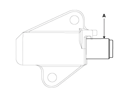
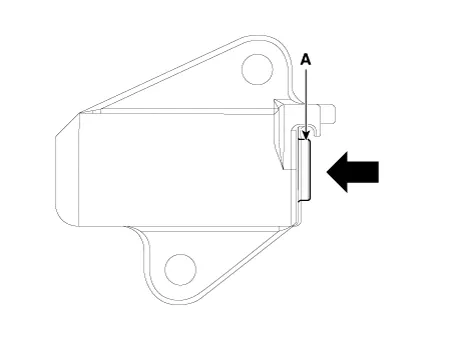
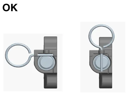
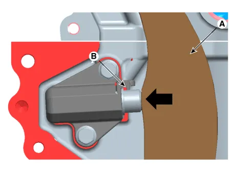
| 5. | Install the timing chain tensioner (A) and remove the stopper pin.
|
| 6. | Install the other parts in the reverse order of removal. |
| 7. | Add all the necessary fluids and check for leaks. Connect GDS. Check for codes, note, and clear. Recheck.
|
Components1. Timing chain2. Timing chain guide3. Timing chain tensioner arm4. Timing chain tensioner
Other information:
Hyundai Ioniq (AE) 2017-2022 Service & Repair Manual: Heater Unit. Components and components location
Component Location1. Heater unit assemblyCompoents1. Heater core cover2. Heater core & Seal assembly3. Mode actuator [LH]4. Temperature control actuator [LH]5. Shower duct [LH]6. Duct sensor [Floor]7. PTC Heater8. Duct sensor [Vent]9. Heater & Evaporator lower case10.
Hyundai Ioniq (AE) 2017-2022 Service & Repair Manual: Parking Distance Warning (PDW) Sensor. Repair procedures
Removal1.Disconnect the negative (-) battery terminal.2.Remove the front / rear bumper cover.(Refer to Body - "Front Bumper Cover")(Refer to Body - "Rear Bumper Cover")3.Disconnect the connector (A) from the parking assist sensor.4.Remove the sensor (A) by pulling out both ends of the sensor holder.
Categories
- Manuals Home
- Hyundai Ioniq Owners Manual
- Hyundai Ioniq Service Manual
- Jump Starting
- Engine Control/Fuel System
- Theft-alarm System
- New on site
- Most important about car

Copyright © 2026 www.hioniqae.com - 0.0136