Hyundai Ioniq (AE): Seat Electrical / Air Ventilation Seat. Components and components location
| Component Location |
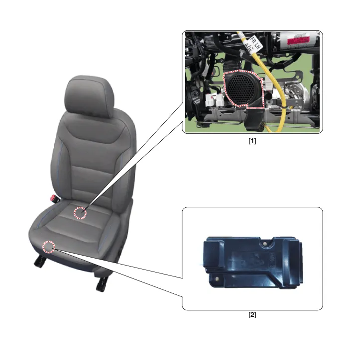
| 1. Ventilation seat unit (Assist seat only) | 2. Ventilation seat blower |
Removal[Front Seat]1.Disconnect the negative (-) battery terminal.2.Remove the floor console upper cover.(Refer to Body - "Floor Console Assembly")3.Remove the seat heater switch after loosening mounting screws.
Circuit Diagram NO Connector A Connector B Connector C 1Ventilation seat unit (IGN1)Driver ventilation LED (Low)Ventilation heater power2Driver bolwer powerDriver ventilation LED (mid)Driver heater power3Driver bolwer SpeedDriver ventilation LED (High)-4Driver RPM inputDriver NTC (+)Heater ground5heater switch (Driver)-Ventilation heater power6Ventilation switch (Driver)--7-Driver NTC (-)Passenger heater power8Driver heater led (Low)Driver blower ground-9Driver heater led (mid)Driver ventilation LED (Low)-10Driver heater led (High)Driver ventilation LED (mid)Heater ground11Ventilation seat unit (IGN 2)Driver ventilation LED (High)12Passenger blower powerPassenger NTC (+)13Passenger blower speed-14Passenger blower RPM input-15Passenger heater switchPassenger NTC (-)16Passenger ventilation switchPassenger blower ground17-18Passenger ventilation LED (Low)19Passenger ventilation LED (mid)20Passenger ventilation LED (High)
Other information:
Hyundai Ioniq (AE) 2017-2022 Service & Repair Manual: PTC Heater. Description and operation
DescriptionThe PTC (Positive Temperature Coefficient) heater is installed at the exit or the backside of the heater core.The PTC heater is an electric heater using a PTC element as an auxiliary heating device that supplements deficiency of interior heat source in highly effective hybrid engine.
Hyundai Ioniq (AE) 2017-2022 Service & Repair Manual: Special service tools
Special Service Tools Tool Name / Number Illustration Description LKA Compensator(09964-C1100)Used for compensating front view camera unitBCW Sensor Correction Tool Set(09958-3T500)Used to correct the blind-spot radar unit.
Categories
- Manuals Home
- Hyundai Ioniq Owners Manual
- Hyundai Ioniq Service Manual
- Engine Control/Fuel System
- DCT(Dual Clutch Transmission) System
- Engine Clutch System
- New on site
- Most important about car
