Hyundai Ioniq (AE): Seat Electrical / Air Ventilation Seat. Repair procedures
| Removal |
| 1. | Disconnect the negative (-) battery terminal. |
| 2. | Remove the front seat. (Refer to Body - "Front Seat Assembly") |
| 3. | Remove the blower duct.
|
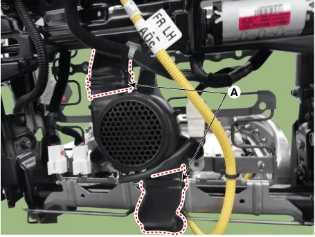
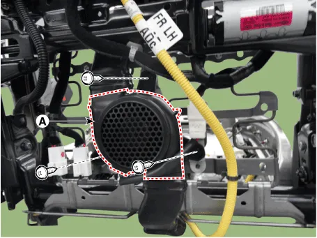
| 4. | Remove the blower FAN (A) after removing the screws.
|
| 1. | Disconnect the negative (-) battery terminal. |
| 2. | Remove the front seat. (Refer to Body - "Front seat Assembly") |
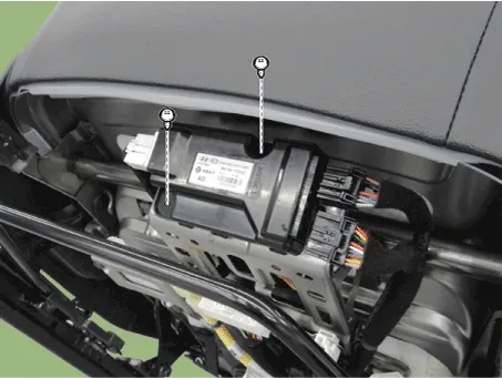
| 3. | Loosening the screws from the ventilation seat unit.
|
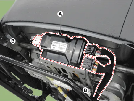
| 4. | Remove the ventilation seat unit (A) after disconnect the connectors (B).
|
| Installation |
| 1. | Install the blower fan. |
| 2. | Install the duct. |
| 3. | Install the front seat assembly. |
| 4. | Connect the negative (-) battery terminal. |
| 1. | Install the ventilation seat unit. |
| 2. | Install the front seat assembly. |
| 3. | Connect the negative (-) battery terminal. |
| Inspection |
| 1. | You can enter the diagnosis mode by turning the heater seat button on. |
| 2. | You can enter the diagnosis mode by referring to following description. |
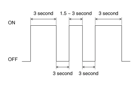
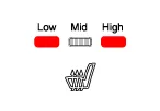
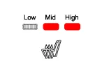
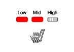
| 3. | Press the heating wire switch as shown below.
|
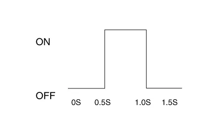
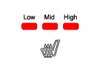
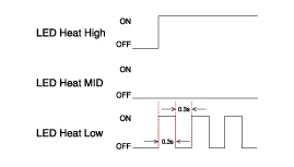
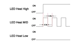
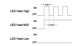
| 4. | When the vehicle enters the diagnostic mode, the three LEDs (Low, Mid, High) in the heating wire section blinks once for 0.5 seconds.
|
| 5. | After entering the diagnostic mode, check the LED status to identify the error.
|
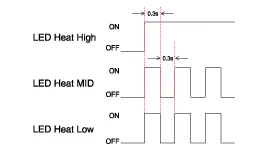
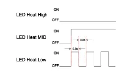
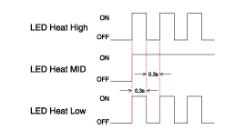
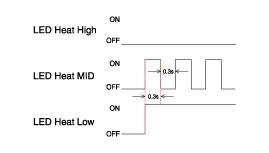
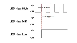
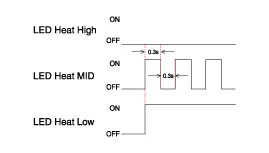
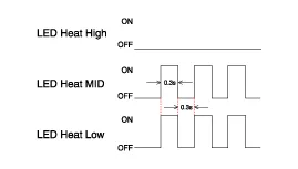
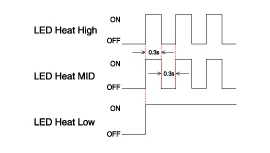
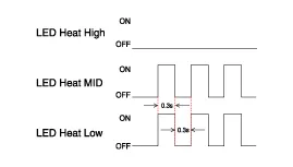
| 6. | You can check the malfunctioning by checking the blinking LED. |
| 7. | The failure data is recorded to the memory by the ventilation seat unit. |
| 8. | Press the heating wire seat switch on the passenger side for 5 seconds or more to make the LED blink four times and delete the failure data in the memory. |
| 9. | Pressing the IGN OFF button will end the diagnosis mode for the heater seat. |
| 10. | You can check whether the heating seat system works properly after turning the IGN ON. If you want to check the error code, you can refer to the procedure of 2 above. |
Circuit Diagram NO Connector A Connector B Connector C 1Ventilation seat unit (IGN1)Driver ventilation LED (Low)Ventilation heater power2Driver bolwer powerDriver ventilation LED (mid)Driver heater power3Driver bolwer SpeedDriver ventilation LED (High)-4Driver RPM inputDriver NTC (+)Heater ground5heater switch (Driver)-Ventilation heater power6Ventilation switch (Driver)--7-Driver NTC (-)Passenger heater power8Driver heater led (Low)Driver blower ground-9Driver heater led (mid)Driver ventilation LED (Low)-10Driver heater led (High)Driver ventilation LED (mid)Heater ground11Ventilation seat unit (IGN 2)Driver ventilation LED (High)12Passenger blower powerPassenger NTC (+)13Passenger blower speed-14Passenger blower RPM input-15Passenger heater switchPassenger NTC (-)16Passenger ventilation switchPassenger blower ground17-18Passenger ventilation LED (Low)19Passenger ventilation LED (mid)20Passenger ventilation LED (High)
Removal1.Disconnect the negative (-) battery terminal.2.Remove the front seat assembly.(Refer to Body - "Front Seat Assembly")3.Remove the seat back.(Refer to Body - "Front Seat Back Cover")4.
Other information:
Hyundai Ioniq (AE) 2017-2022 Service & Repair Manual: Warning Indicator. Repair procedures
RemovalWarning Indicator1.Disconnect the negative (-) battery terminal.2.Remove the mirror (A).InstallationWarning Indicator1.Install the outside mirror.2.Connect the negative (-) battery terminal.Inspection1.Apply battery voltage to each terminal as shown in the table and verify that the mirror operates properly.
Hyundai Ioniq (AE) 2017-2022 Service & Repair Manual: Cruise Control Switch. Repair procedures
Removal1.Disconnect the negative (-) battery terminal.2.Remove the steering wheel assembly.(Refer to Steering System - "Steering Wheel")3.Remove the steering back cover (A).4.Remove the steering remote control connector (A).5.Remove the steering remote control after loosening the screws.
Categories
- Manuals Home
- Hyundai Ioniq Owners Manual
- Hyundai Ioniq Service Manual
- Body (Interior and Exterior)
- DCT(Dual Clutch Transmission) System
- Repair procedures
- New on site
- Most important about car
