Hyundai Ioniq (AE): Audio / Audio Remote Control. Repair procedures
Hyundai Ioniq (AE) 2017-2022 Service & Repair Manual / Body Electrical System / Audio / Audio Remote Control. Repair procedures
| Inspection |
| 1. | Check for resistance between terminals in each switch position (LH).
[LH : Audio+B/TOOTH+VOICE]
|
| 2. | Check for resistance between terminals in each switch position (RH).
[RH : Trip+Cruise+SCC]
|
| Removal |
| 1. | Disconnect the negative (-) battery terminal. |
| 2. | Remove the steering wheel assembly. (Refer to Steering System - "Steering Wheel") |
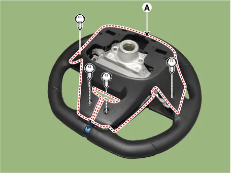
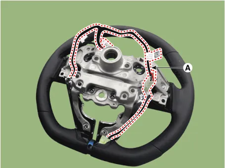
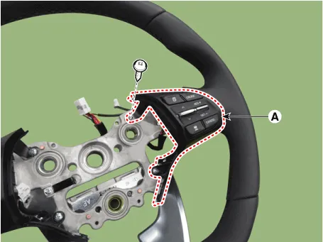
| 3. | Remove the steering back cover (A).
|
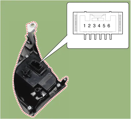
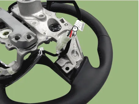
| 4. | Remove the steering remote control connector (A).
|
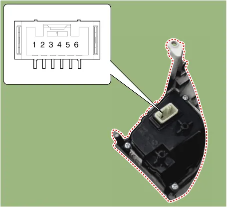
| 5. | Remove the steering remote control after loosening the screws.
|
| Installation |
| 1. | Install the steering wheel remote control after connecting the connector. |
| 2. | Connect the negative (-) battery terminal. |
Circuit Diagram[Audio+B/Tooth][Audio+B/Tooth+Voice][Trip][Trip+Cruise][Trip+Cruise+SCC]
Circuit Diagram
Other information:
Hyundai Ioniq (AE) 2017-2022 Service & Repair Manual: Evaporator Temperature Sensor. Repair procedures
Inspection1.Turn the ignition switch OFF.2.Disconnect the evaporator temperature sensor connector.3.Measure the resistance between terminal "+" and "-" of the evaporator temperature sensor.Specification Evaporator core temperature [°C (°F)] Resistance [KΩ]
Hyundai Ioniq (AE) 2017-2022 Service & Repair Manual: Schematic diagrams
System Block DiagramComponent Parts and Function Outline Component part Function Vehicle-speed sensor, ESP/ABS Control ModuleConverts vehicle speed to pulse.VCUReceives signals from sensor and control switches.
Categories
- Manuals Home
- Hyundai Ioniq Owners Manual
- Hyundai Ioniq Service Manual
- Theft-alarm System
- Jump starting procedure
- Repair procedures
- New on site
- Most important about car

Copyright © 2026 www.hioniqae.com - 0.0229