Hyundai Ioniq (AE): Button Engine Start System / Components and components location
Hyundai Ioniq (AE) 2017-2022 Service & Repair Manual / Body Electrical System / Button Engine Start System / Components and components location
| Component Location |
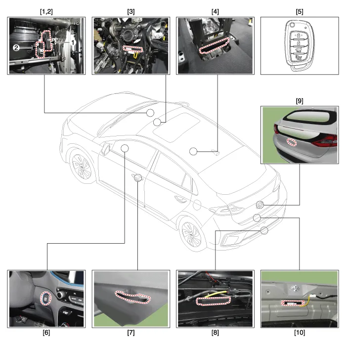
| 1. Smart key unit 2. Body control module (BCM) 3. Interior antenna 1 4. Interior antenna 2 5. FOB Key | 6. Start Stop Button (SSB) 7.Door handle & Door antenna 8. Bumper antenna 9. Trunk lid switch 10. Trunk antenna |
Circuit Diagram
Other information:
Hyundai Ioniq (AE) 2017-2022 Service & Repair Manual: Heater Unit. Repair procedures
Replacement When prying with a flat-tip screwdriver or use a prying trim tool, wrap it with protective tape, and apply protective tape around the related parts, to prevent damage.1.Disconnect the negative (-) battery terminal.2.Recover the refrigerant with a recovery / recycling / charging station.
Hyundai Ioniq (AE) 2017-2022 Service & Repair Manual: emperature Control Actuator. Repair procedures
Inspection1.Turn the ignition switch OFF.2.Disconnect the temperature control actuator connector.3.Verify that the temperature control actuator operates to the cool position when connecting 12V to terminal 3 and grounding terminal 7.Verify that the temperature control actuator operates to the warm position when connected in reverse.
Categories
- Manuals Home
- Hyundai Ioniq Owners Manual
- Hyundai Ioniq Service Manual
- Maintenance
- If the 12 Volt Battery is Discharged (Hybrid Vehicle)
- Jump starting procedure
- New on site
- Most important about car

Copyright © 2026 www.hioniqae.com - 0.0147