
Hyundai Ioniq (AE): Low Voltage DC/DC Converter (LDC) / Components and components location
| Component Location |
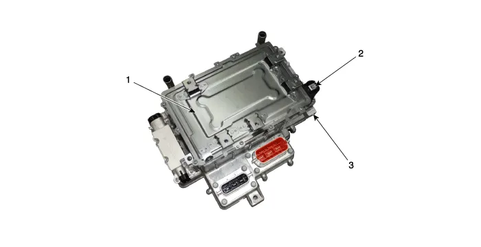
| 1. Low Voltage DC/DC Converter (LDC) 2. Power Outlet Terminal (DC 12V) | 3. Ground Terminal |
Specification Item Specification Input Voltage (V)200 - 310Output Voltage (V)12.8 - 14.7Rated Power (kW)1.
Schematic Diagram
Other information:
Hyundai Ioniq (AE) 2017-2022 Service & Repair Manual: Auto Defogging Sensor. Description and operation
DescriptionThe auto defogging sensor is installed on the front window glass. The sensor judges and sends signal if moisture occurs to blow out wind for defogging. The air conditioner control module receives signal from the sensor and restrains moisture and eliminate defog by controlling the intake actuator, A/C, auto defogging actuator, blower moto
Hyundai Ioniq (AE) 2017-2022 Service & Repair Manual: Rear Corner Safety ON/OFF Switch. Repair procedures
Inspection1.Disconnect the negative (-) battery terminal.2.Remove the crash pad lower panel.(Refer to Body - "Crash Pad Lower Panel")3.Remove the lower crash pad switch assembly (A) after disengaging the mounting clip.4.Remove the rheostat switch connector (A).
Categories
- Manuals Home
- Hyundai Ioniq Owners Manual
- Hyundai Ioniq Service Manual
- Engine Clutch System
- Body (Interior and Exterior)
- Jump starting procedure
- New on site
- Most important about car
