Hyundai Ioniq (AE): High Voltage Battery Cooling System / Cooling Fan. Repair procedures
| Removal |
|

| 1. | Shut off the high voltage. (Refer to Hybrid Control System - "High Voltage Shut-off Procedures") |
| 2. | Remove the rear seat cushion. (Refer to Body - "Rear Seat Assembly") |
| 3. | Remove the rear door scuff trim. (Refer to Body - "Door Scuff Trim") |
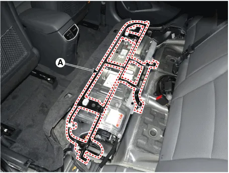
| 4. | Remove the upper frame (A) after loosening the mounting bolts and nuts.
|
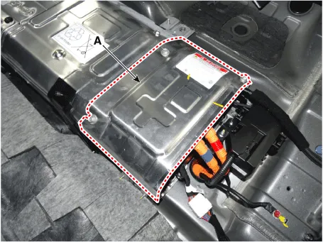
| 5. | Remove the high voltage battery rear cover (A) after loosening the mounting bolts and nuts.
|
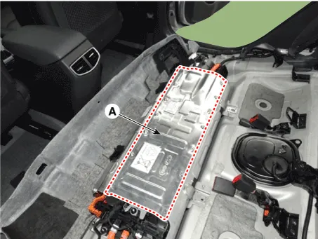
| 6. | Remove the high voltage battery front cover (A) after loosening the mounting bolts and nuts.
|
| 7. | Remove the outlet cooling duct. (Refer to Hybrid Control System - "Cooling Duct") |
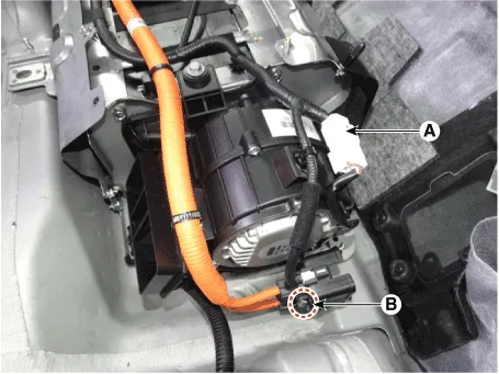
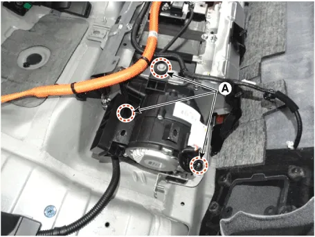
| 8. | Disconnect the cooling fan connector (A). |
| 9. | Remove the safety plug cable after loosening the mounting nuts (B).
|
| 10. | Remove the cooling fan after loosening the mounting bolts and nuts (A).
|
| Installation |
|
| 1. | Install the cooling fan in the reverse order of removal.
|
| Inspection |
| 1. | Connect the GDS to the Data Link Connector (DLC). |
| 2. | Connect the oscilloscope probe to the BMS extension connectors.
|
| 3. | Turn the ignition switch ON. |
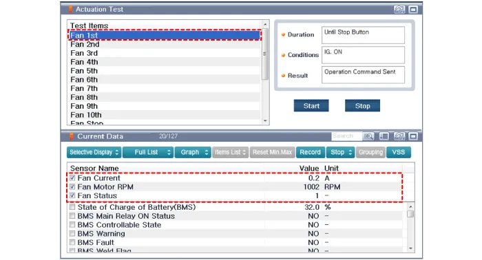
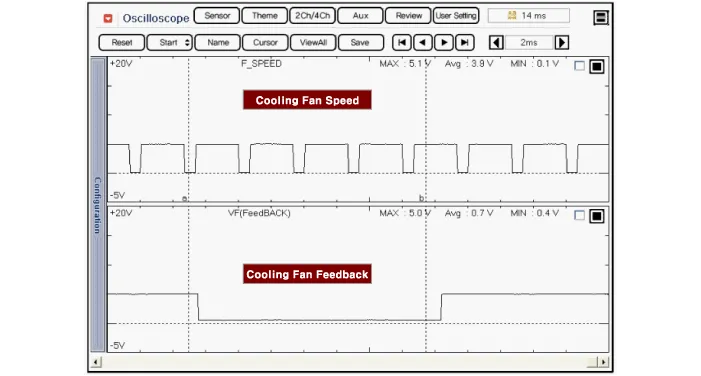
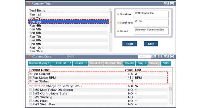
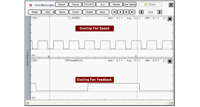
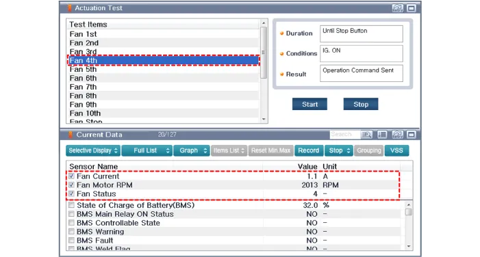
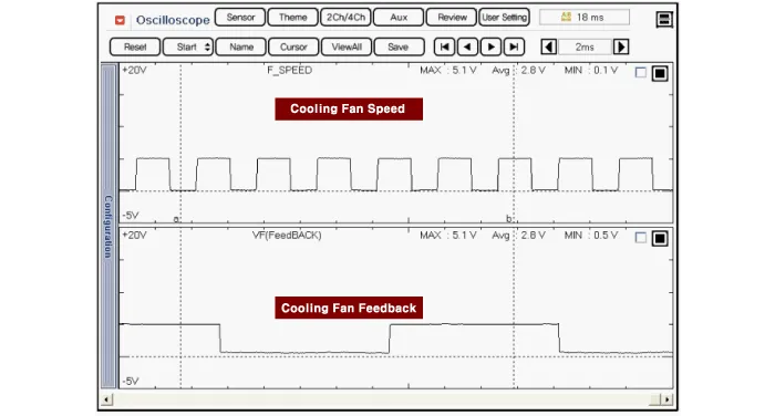
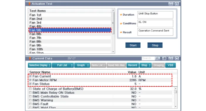
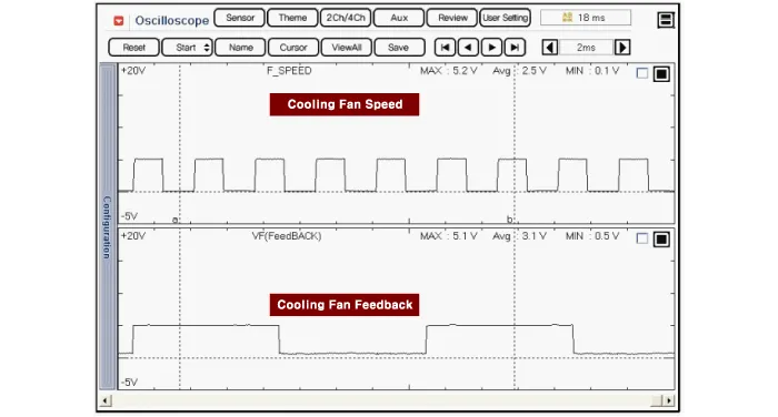
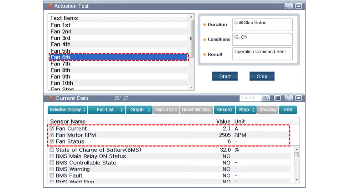
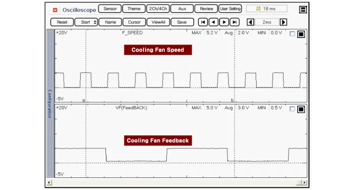
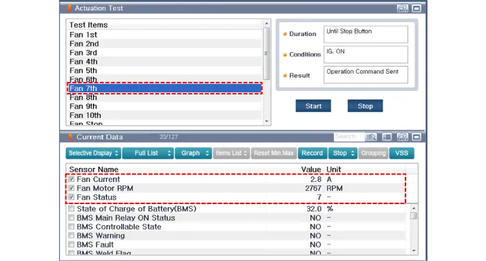
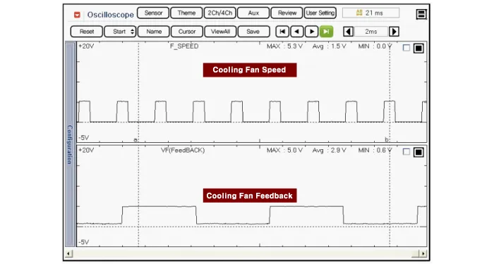
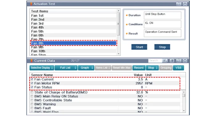
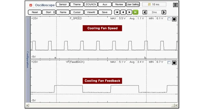
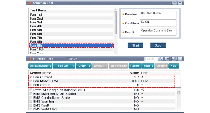
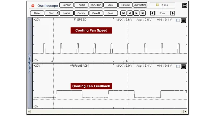
| 4. | Check "Fan Status", "Current" "Waveform" and waveforms in each cooling fan operation mode by using "Actuation Test" function in GDS.
[Cooling Fan at 1st]
[Cooling Fan at 2st]
[Cooling Fan at 3st]
[Cooling Fan at 4st]
[Cooling Fan at 5st]
[Cooling Fan at 6st]
[Cooling Fan at 7st]
[Cooling Fan at 8st]
[Cooling Fan at 9st]
|


Components1. Main Connector2. BLDC Motor
Removal • Be sure to read and follow the "General Safety Information and Caution" before doing any work related with the high voltage system.
Other information:
Hyundai Ioniq (AE) 2017-2022 Service & Repair Manual: emperature Control Actuator. Description and operation
DescriptionThe temperature control actuator is located at the heater unit. It regulates the temperature by the procedure as follows. The signal from the control unit adjusts the position of the temperature door by operating the temperature switch. Then the temperature will be regulated by the hot/cold air ratio decided by the position of the temper
Hyundai Ioniq (AE) 2017-2022 Service & Repair Manual: Intake Actuator. Repair procedures
Inspection1.Turn the ignition switch OFF.2.Disconnect the intake actuator connector.3.Verify that the intake actuator operates to the fresh position when connecting 12V to terminal 3 and grounding terminal 4.Verify that the intake actuator operates to the recirculation position when connected in reverse.
Categories
- Manuals Home
- Hyundai Ioniq Owners Manual
- Hyundai Ioniq Service Manual
- Theft-alarm System
- Checking the Coolant Level
- Suspension System
- New on site
- Most important about car
