Hyundai Ioniq (AE): Parking Brake System / Electric Parking Brake (EPB). Components and components location
| Components |
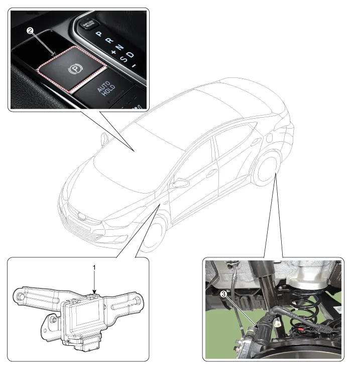
| 1. Electric parking brake comtrol module 2. EPB Switch | 3. EPB Actuator |
DescriptionThe EPB is an electronic parking brake. The EPB is different from existing parking systems which operated with the brake pedal or the lever type.
System Circuit DiagramTerminal Function Pin No Function Pin No Function 1-21-2-22-3- 23C-CAN (Low)4- 24C-CAN (High) 5- 25EPB Switch (SW1)6- 26EPB Switch (SW2)7- 27EPB Switch (SW3)8-28EPB Switch (SW4)9- 29-10- 30- 11- 31- 12- 32- 13- 33ì ‘ì§€ 14- 34ì ‘ì§€15- 35EPB Actuator RH (+)16- 36EPB Actuator LH (-)17IGNITION_137EPB Actuator RH (-)18-38EPB Actuator LH (+)19-39Battary20-40Battary
Other information:
Hyundai Ioniq (AE) 2017-2022 Service & Repair Manual: A/C Pressure Transducer. Description and operation
DescriptionThe A/C Pressure Transducer (APT) converts the pressure value of high pressure line into voltage value after measuring it. By converted voltage value, engine ECU controls the cooling fan by operating it high speed or low speed. Engine ECU stops the operation of the compressor when the temperature of refrigerant line is very high or very
Hyundai Ioniq (AE) 2017-2022 Service & Repair Manual: Components and components location
C
Categories
- Manuals Home
- Hyundai Ioniq Owners Manual
- Hyundai Ioniq Service Manual
- General Information
- Repair procedures
- Suspension System
- New on site
- Most important about car
