Hyundai Ioniq (AE): Parking Brake System / Electric Parking Brake (EPB). Schematic diagrams
Hyundai Ioniq (AE) 2017-2022 Service & Repair Manual / Brake System / Parking Brake System / Electric Parking Brake (EPB). Schematic diagrams
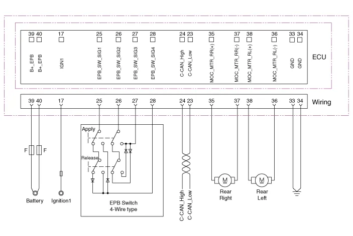
| System Circuit Diagram |
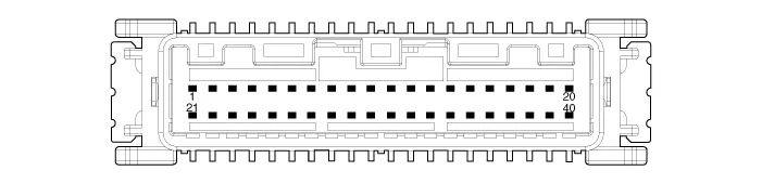
| Terminal Function |
|
Pin No
|
Function
|
Pin No
|
Function
|
| 1 | - | 21 | - |
| 2 | - | 22 | - |
| 3 | - | 23 | C-CAN (Low) |
| 4 | - | 24 | C-CAN (High) |
| 5 | - | 25 | EPB Switch (SW1) |
| 6 | - | 26 | EPB Switch (SW2) |
| 7 | - | 27 | EPB Switch (SW3) |
| 8 | - | 28 | EPB Switch (SW4) |
| 9 | - | 29 | - |
| 10 | - | 30 | - |
| 11 | - | 31 | - |
| 12 | - | 32 | - |
| 13 | - | 33 | ě ‘ě§€ |
| 14 | - | 34 | ě ‘ě§€ |
| 15 | - | 35 | EPB Actuator RH (+) |
| 16 | - | 36 | EPB Actuator LH (-) |
| 17 | IGNITION_1 | 37 | EPB Actuator RH (-) |
| 18 | - | 38 | EPB Actuator LH (+) |
| 19 | - | 39 | Battary |
| 20 | - | 40 | Battary |
Components1. Electric parking brake comtrol module2. EPB Switch3. EPB Actuator
Removal1.Turn ignition switch off and disconnect the battery (-) cable from the battery.2.Disconnect the EPB control module connector.3.Loosen the mounting nuts and then remove the EPB control module.
Other information:
Hyundai Ioniq (AE) 2017-2022 Service & Repair Manual: Repair procedures
Replacement1.Remove the battery (-) terminal.2.Remove the engine room under cover.(Refer to Engine Mechanical System - "Engine Room Under Cover")3.Remove the heater hose (A) and AEWP hose (B).4.Disconnect the lock pin to remove the heater hose pump connector (A).
Hyundai Ioniq (AE) 2017-2022 Service & Repair Manual: Specifications
S
Categories
- Manuals Home
- Hyundai Ioniq Owners Manual
- Hyundai Ioniq Service Manual
- Heating, Ventilation and Air Conditioning
- Suspension System
- Engine Clutch System
- New on site
- Most important about car

Copyright © 2026 www.hioniqae.com - 0.0178