Hyundai Ioniq (AE): Parking Brake System / Electric Parking Brake (EPB). Components and components location
| Components |
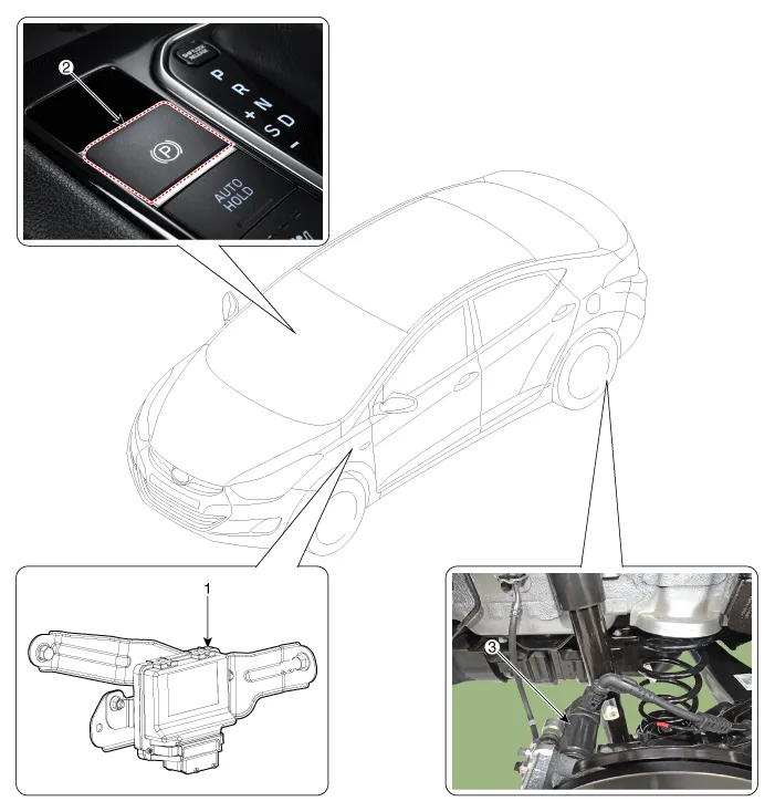
| 1. Electric parking brake comtrol module 2. EPB Switch | 3. EPB Actuator |
DescriptionThe EPB is an electronic parking brake. The EPB is different from existing parking systems which operated with the brake pedal or the lever type.
System Circuit DiagramTerminal Function Pin No Function Pin No Function 1-21-2-22-3- 23C-CAN (Low)4- 24C-CAN (High) 5- 25EPB Switch (SW1)6- 26EPB Switch (SW2)7- 27EPB Switch (SW3)8-28EPB Switch (SW4)9- 29-10- 30- 11- 31- 12- 32- 13- 33ě ‘ě§€ 14- 34ě ‘ě§€15- 35EPB Actuator RH (+)16- 36EPB Actuator LH (-)17IGNITION_137EPB Actuator RH (-)18-38EPB Actuator LH (+)19-39Battary20-40Battary
Other information:
Hyundai Ioniq (AE) 2017-2022 Service & Repair Manual: Heater Unit. Repair procedures
Replacement When prying with a flat-tip screwdriver or use a prying trim tool, wrap it with protective tape, and apply protective tape around the related parts, to prevent damage.1.Disconnect the negative (-) battery terminal.2.Recover the refrigerant with a recovery / recycling / charging station.
Hyundai Ioniq (AE) 2017-2022 Service & Repair Manual: Intake Actuator. Repair procedures
Inspection1.Turn the ignition switch OFF.2.Disconnect the intake actuator connector.3.Verify that the intake actuator operates to the fresh position when connecting 12V to terminal 3 and grounding terminal 4.Verify that the intake actuator operates to the recirculation position when connected in reverse.
Categories
- Manuals Home
- Hyundai Ioniq Owners Manual
- Hyundai Ioniq Service Manual
- Hybrid Vehicle Engine Compartment
- Repair procedures
- Engine Mechanical System
- New on site
- Most important about car
