Hyundai Ioniq (AE): Parking Brake System / Electric Parking Brake (EPB). Repair procedures
| Removal |
| 1. | Turn ignition switch off and disconnect the battery (-) cable from the battery. |
| 2. | Disconnect the EPB control module connector.
|
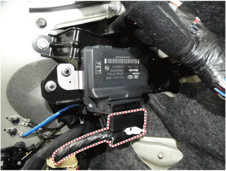
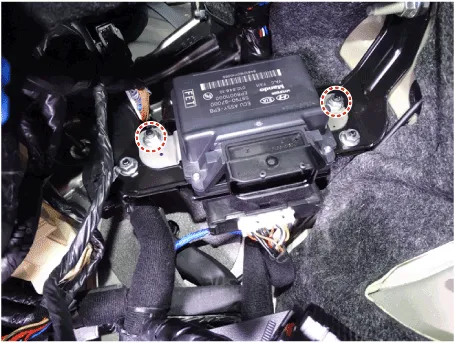
| 3. | Loosen the mounting nuts and then remove the EPB control module.
|
| Installation |
| 1. | Install in the reverse order of removal. |
| 2. | Check that the brake operates normally by pushing the EPB switch more than 3 times after installing the EPB module. |
System Circuit DiagramTerminal Function Pin No Function Pin No Function 1-21-2-22-3- 23C-CAN (Low)4- 24C-CAN (High) 5- 25EPB Switch (SW1)6- 26EPB Switch (SW2)7- 27EPB Switch (SW3)8-28EPB Switch (SW4)9- 29-10- 30- 11- 31- 12- 32- 13- 33ě ‘ě§€ 14- 34ě ‘ě§€15- 35EPB Actuator RH (+)16- 36EPB Actuator LH (-)17IGNITION_137EPB Actuator RH (-)18-38EPB Actuator LH (+)19-39Battary20-40Battary
Other information:
Hyundai Ioniq (AE) 2017-2022 Service & Repair Manual: Blower Motor. Repair procedures
Inspection1.Connect the battery voltage and check the blower motor rotation.2.If the blower motor does not operate well, substitute with a known-good blower motor and check for proper operation.3.Replace the blower motor if it is proved that there is a problem with it.
Hyundai Ioniq (AE) 2017-2022 Service & Repair Manual: Components and components location
C
Categories
- Manuals Home
- Hyundai Ioniq Owners Manual
- Hyundai Ioniq Service Manual
- Suspension System
- Transmission Gear Oil. Repair procedures
- Jump starting procedure
- New on site
- Most important about car
