Hyundai Ioniq (AE): Hybrid Motor Cooling System / Electric Water Pump(EWP). Components and components location
| Component location |
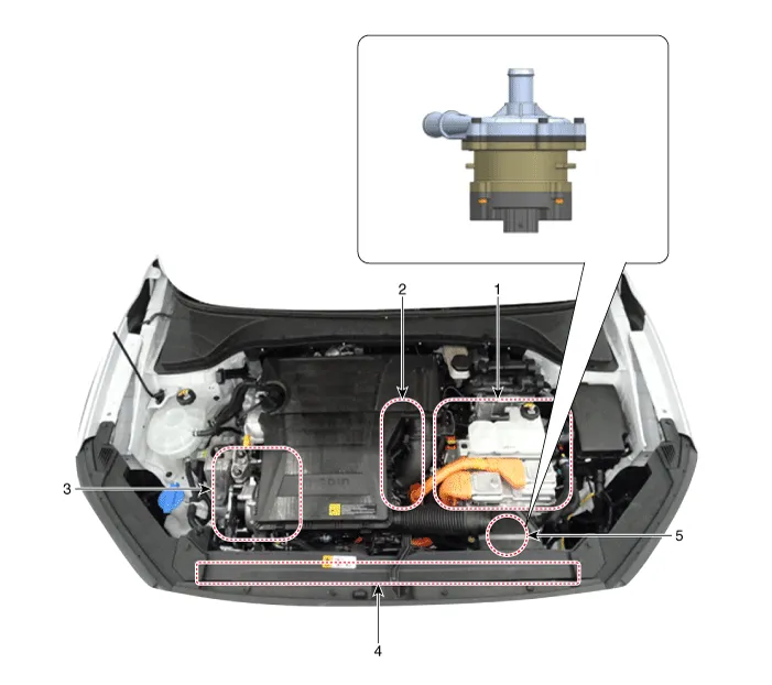
| 1. HPCU (Hybrid Power Control Unit) (LDC+MCU+HCU+Reservoir) 2. Hybrid drive motor | 3. Hybrid starter generator (HSG) 4. Electrical radiator 5. Electric water pump (EWP) |
Description• Function : It circulates the coolant for the hybrid system (HPCU, drive motor, and HSG).• Operating Principles: When the coolant temperature exceeds the limit set in the MCU in the hybrid system, the motor control unit (MCU) sends a command to the electric water pump (EWP) through the CAN communication to operate the EWP.
Removal1.Remove the 12 V battery (-) cable.2.Remove the undercover.(Refer to Engine Mechanical System - "Engine Room Undercover".)3.Drain the coolant from the hybrid cooling system.
Other information:
Hyundai Ioniq (AE) 2017-2022 Service & Repair Manual: Description and operation
DescriptionIn ordinary cars, the mechanical water pump mounted on the engine for heating purposes is activated to circulate the cooling water, but in hybrid cars, AEWP is used to circulate the cooling water when the engine is not operating. Classification System Cooling water used
Hyundai Ioniq (AE) 2017-2022 Service & Repair Manual: High voltage shut-off procedures
High Voltage Shut-off Procedures • Be sure to read and follow the "General Safety Information and Caution" before doing any work related with the high voltage system. Failure to follow the safety instructions may result in serious electrical injuries.
Categories
- Manuals Home
- Hyundai Ioniq Owners Manual
- Hyundai Ioniq Service Manual
- Checking the Coolant Level
- Engine Clutch System
- Hybrid Vehicle Engine Compartment
- New on site
- Most important about car
