
Hyundai Ioniq (AE): Front Suspension System / Front Strut Assembly. Repair procedures
| Removal |
| 1. | Loosen the wheel nuts slightly. Raise the vehicle, and make sure it is securely supported. |
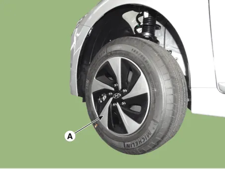
| 2. | Remove the front wheel and tire (A) from the front hub.
|

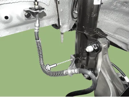
| 3. | Loosen the brake hose mounting bolt and then remove the brake hose bracket.
|
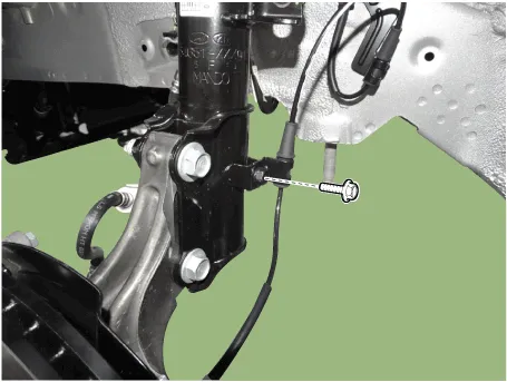
| 4. | Loosen the mounting holt and then remove the brake hose from the strut assembly.
|
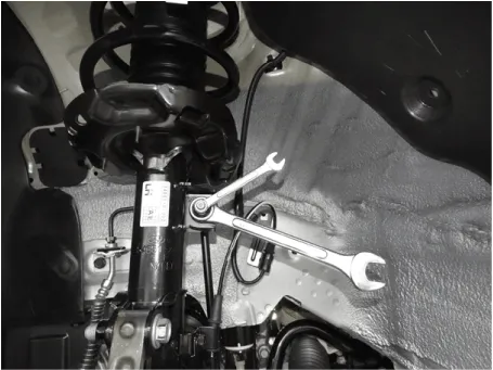
| 5. | Disconnect the stabilizer link with the front strut assembly after loosening the nut.
|
| 6. | Remove the cowl top cover. (Refer to Body - "Cowl Top Cover") |
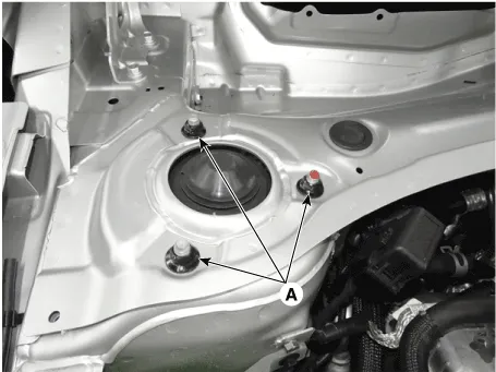
| 7. | Loosen the upper strut mounting nut (A).
|
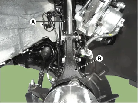
| 8. | Remove the front strut assembly (A) from the front axle (B) by loosening the bolts & nuts.
|
| 9. | Install in the reverse order of removal. |
| Disassembly |
|

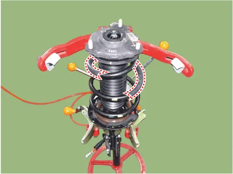
| 1. | Using spring comperssor, compress the coil spring (A)
|
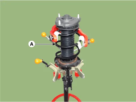
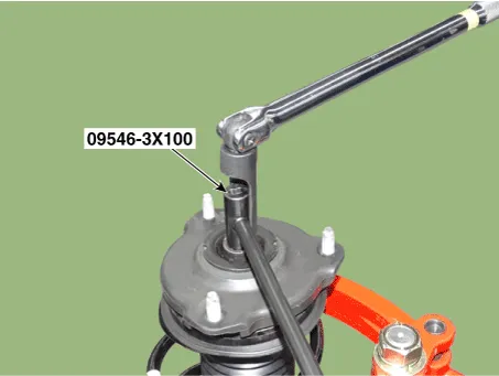
| 2. | Using the special tool (09546-3X100), remove the self locking nut.
|
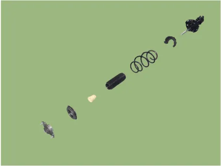
| 3. | Remove the insulator, strut bearing, coil spring and dust cover from the strut assembly.
|
| Inspection |
| 1. | Check the strut bearing for wear and damage. |
| 2. | Check the spring upper and lower pad for damage and deterioration. |
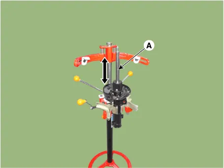
| 3. | Compress and extend the piston rod (A) and check that there is no abnormal resistance or unusual sound during operation.
|
| Disposal |
| 1. | Fully extend the piston rod. |
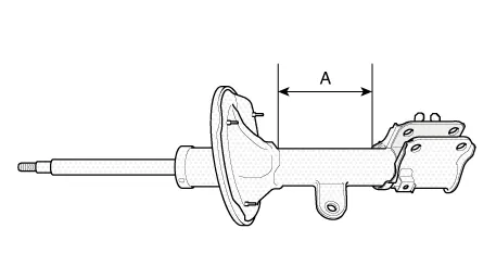
| 2. | Drill a hole on the (A) section to remove gas from the cylinder.
|

| Reassembly |
| 1. | Install in the reverse order of removal. |
| 2. | Compress and extend the piston rod (A) and check that there is no abnormal resistance or unusual sound during operation.
|
| 3. | Using the special tool (09546-3X100), install the self locking nut.
|
Components1. Strut assembly2. Lock nut3. Insulator 4. Strut bearing & Spring upper pad5. Bumper rubber6. Dust cover7. Coli spring8. Spring lower pad
Removal1.Loosen the wheel nuts slightly.Raise the vehicle, and make sure it is securely supported.2.Remove the front wheel and tire (A) from the front hub.
Other information:
Hyundai Ioniq (AE) 2017-2022 Service & Repair Manual: Photo Sensor. Description and operation
Description The photo sensor is located at the center of the defrost nozzles.The photo sensor contains a photovoltaic (sensitive to sunlight) diode. The solar radiation received by its light receiving portion, generates an electromotive force in proportion to the amount of radiation received which is transferred to the automatic temperature control
Hyundai Ioniq (AE) 2017-2022 Service & Repair Manual: Repair procedures
Self Diagnosis1.Self-diagnosis process. • When operating the self-diagnostics, the below fault (self-diagnostics code) will blink at 0.5 seconds interval on the temperature display settings (driver's side only) and the remaining symbols are OFF .
Categories
- Manuals Home
- Hyundai Ioniq Owners Manual
- Hyundai Ioniq Service Manual
- Maintenance
- Hybrid Vehicle Engine Compartment
- Engine Clutch System
- New on site
- Most important about car
