Hyundai Ioniq (AE): Emergency Call System / Emergency Call (eCall) Button. Repair procedures
Hyundai Ioniq (AE) 2017-2022 Service & Repair Manual / Body Electrical System / Emergency Call System / Emergency Call (eCall) Button. Repair procedures
| Removal |
| 1. | Disconnect the negative (-) battery terminal. |
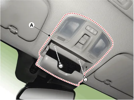
| 2. | separate the overhead console (A) from the roof trim after loosening the mounting screws.
|
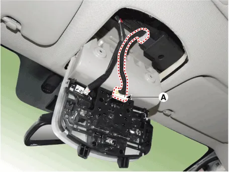
| 3. | Remove the overhead console (A) after disconnecting the connector (A)
|
| Installation |
| 1. | Install the overhead console assembly after connecting the connector. |
| 2. | Connect the negative (-) battery terminal. |
SCHEMATIC DIAGRAM
ComponentsRADIO+GNSS+eCallRADIO+GNSS+DAB+eCall
Other information:
Hyundai Ioniq (AE) 2017-2022 Service & Repair Manual: Photo Sensor. Description and operation
Description The photo sensor is located at the center of the defrost nozzles.The photo sensor contains a photovoltaic (sensitive to sunlight) diode. The solar radiation received by its light receiving portion, generates an electromotive force in proportion to the amount of radiation received which is transferred to the automatic temperature control
Hyundai Ioniq (AE) 2017-2022 Service & Repair Manual: Description and operation
DescriptionBlcok DiagramFunctions of Front View CameraFront View Camera supports the following functions using the information (lane, light source, vehicle and pedestrian) detected by the front view camera and the vehicle's signal information (CAN communication).
Categories
- Manuals Home
- Hyundai Ioniq Owners Manual
- Hyundai Ioniq Service Manual
- DCT(Dual Clutch Transmission) System
- Front Disc Brake. Repair procedures
- Transmission Gear Oil. Repair procedures
- New on site
- Most important about car

Copyright © 2026 www.hioniqae.com - 0.0128