Hyundai Ioniq (AE): Heater / emperature Control Actuator. Repair procedures
| Inspection |
| 1. | Turn the ignition switch OFF. |
| 2. | Disconnect the temperature control actuator connector. |
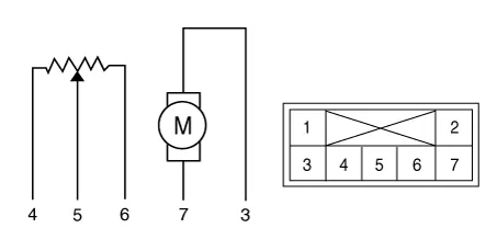
| 3. | Verify that the temperature control actuator operates to the cool position when connecting 12V to terminal 3 and grounding terminal 7. Verify that the temperature control actuator operates to the warm position when connected in reverse.
|
| 4. | Connect the temperature control actuator connector. |
| 5. | Turn the ignition switch ON. |
| 6. | Check the voltage between terminal 5 and 6. |
| 7. | If the measured voltage is not within specification, check the operation by replacing the existing temperature control actuator with a new genuine part. After that, determine whether replacement of the temperature control actuator is required or not. |
| Diagnosis With GDS |
| 1. | The heating, ventilation and air conditioning can be quickly diagnosed failed parts with vehicle diagnostic system (GDS). ※ The diagnostic system (GDS) provides the following information. (1) Self diagnosis : Checking the failure code (DTC) and display. (2) Current data : Checking the system input/output data state. (3) Actuation test : Checking the system operation condition. (4) Additional function : Other controlling such as he system option and zero point adjustment. |
| 2. | Select the 'Car model' and the system to be checked in order to check the vehicle with the tester. |
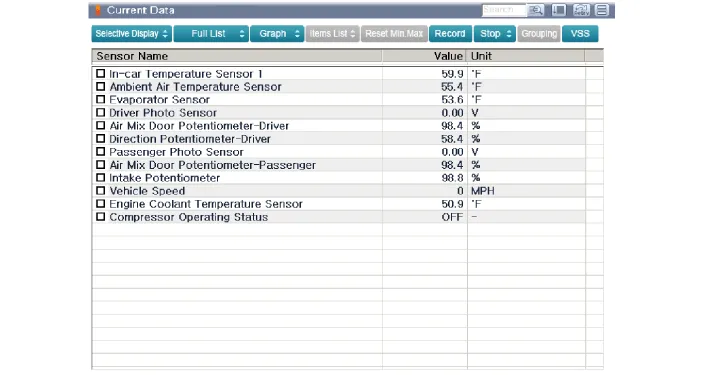
| 3. | Select the 'Current data' menu to search the current state of the input / output data. The input / output data for the sensors corresponding to the Temperature Control Actuator can be checked.
|
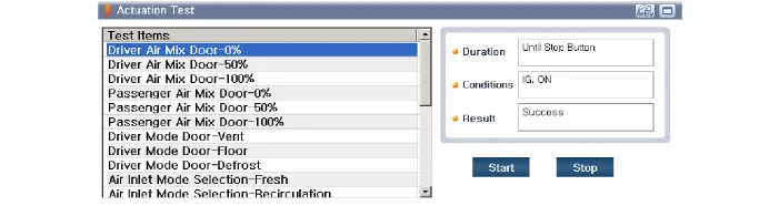
| 4. | To perform compulsory operation on Temperature Control Actuator input factors, select "ACTUATION TEST".
|
| Replacement |
| 1. | Disconnect the negative (-) battery terminal. |
| 2. | Remove the crash pad lower panel. (Refer to Body - "Crash Pad Lower Panel") |
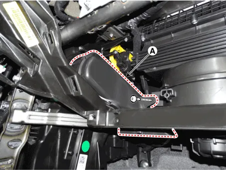
| 3. | Remove the driver's side shower duct (A) after loosening the screw.
|
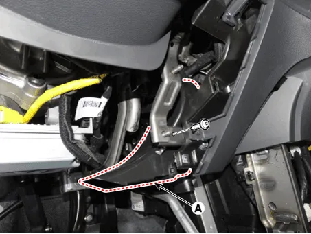
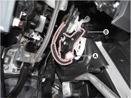
| 4. | Disconnect the connector (A) and then remove the driver's side temperature control actuator (B) after loosening the mounting screws.
|
| 5. | To install, reverse the removal procedure. |
| 1. | Disconnect the negative (-) battery terminal. |
| 2. | Remove the glove box upper cover assembly. (Refer to Body - "Glove Box Upper Cover Assembly") |
| 3. | Remove the passenger's side shower duct (A) after loosening the screw.
|
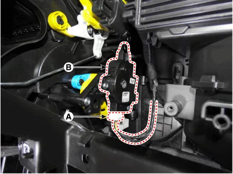
| 4. | Disconnect the connector (A) and then remove the passenger's side temperature control actuator (B) after loosening the mounting screws.
|
| 5. | To install, reverse the removal procedure. |
Specifications Door Position Voltage (V) Error Detecting Vent0.3 ± 0.15Low voltage : 0.
Components Location1. Mode control actuator [LH]2. Mode control actuator [RH]
Other information:
Hyundai Ioniq (AE) 2017-2022 Service & Repair Manual: Repair procedures
Service Point Target Auto Calibration (SPTAC)When you need calibration :– Front view camera is removed and mounted– Replace front view camera with a new one – Windshield glass changed– Front view camera coupler of the windshield glass is deformedService Point T
Hyundai Ioniq (AE) 2017-2022 Service & Repair Manual: Description and operation
System OverviewParking Distance Warning (PDW) is an electronic driving aid that warns the driver to be cautious while parking or driving at low speed. The sensor uses ultrasonic waves to detect objects within proximity of the vehicle.PDW consists of four RPS sensors which are detecting the obstacles and transmit the result separated into three war
Categories
- Manuals Home
- Hyundai Ioniq Owners Manual
- Hyundai Ioniq Service Manual
- Engine Clutch System
- Suspension System
- Hybrid Vehicle Engine Compartment
- New on site
- Most important about car
