Hyundai Ioniq (AE): Clutch System / Engine Clutch Actuator. Repair procedures
Hyundai Ioniq (AE) 2017-2022 Service & Repair Manual / Engine Clutch System / Clutch System / Engine Clutch Actuator. Repair procedures
| Removal |
| 1. | Turn the ignition switch OFF and disconnect the battery (-) terminal. |
| 2. | Remove the engine room under cover. (Refer to Engine Mechanical System - "Engine Room Under Cover") |
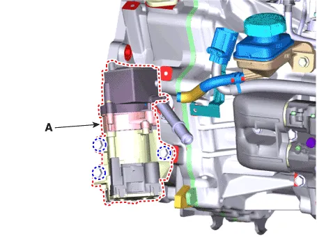
| 3. | Disconnect the engine clutch actuator connector (A).
|

| 4. | Disconnect the reservoir hose (B).
|


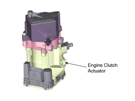
| 5. | Remove the engine clutch actuator (A) from the hybrid motor assembly after loosening the bolts.
|
| Installation |
| 1. | Install in the reverse order of removal.
|

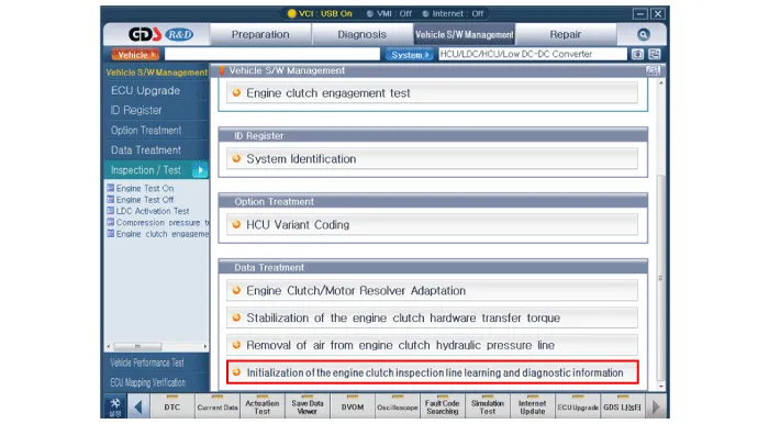
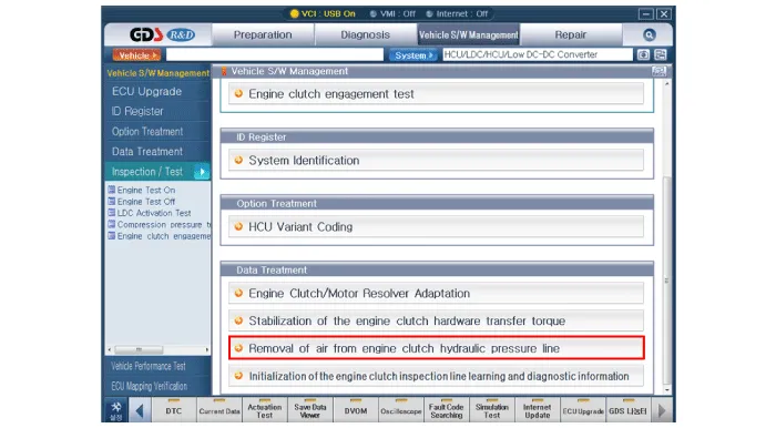
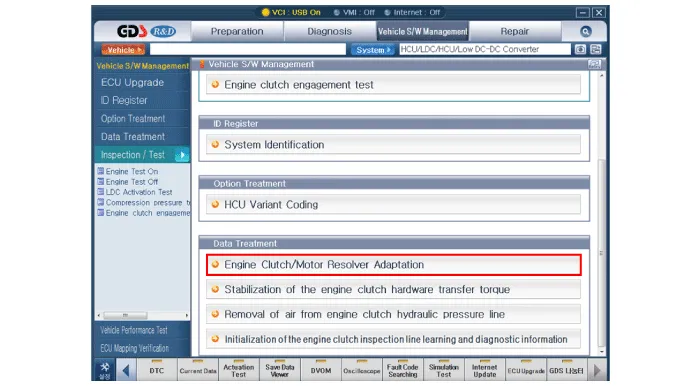
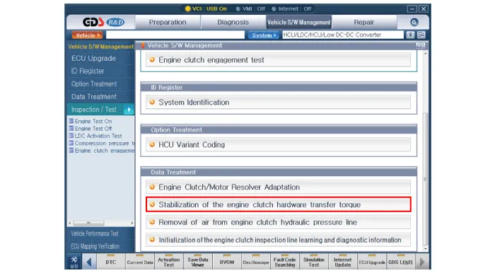
| 2. | After replacing the Engine clutch actuator, operate the followings in order using GDS equipment.
|

Circuit Diagram
Components 1. Clutch disc2. Clutch cover3. Concentric slave cylinder4. Hybrid motor assembly5. Engine clutch actuator6. Reservoir
Other information:
Hyundai Ioniq (AE) 2017-2022 Service & Repair Manual: Evaporator Core. Repair procedures
Replacement1.Disconnect the negative (-) battery terminal. 2.Remove the heater and blower assembly.(Refer to Heater - "Heater Unit") 3.Remove the evaporator core cover (A) after loosening the mounting screws.4.Pull out the evaporator temperature sensor (A) from the evaporator core.
Hyundai Ioniq (AE) 2017-2022 Service & Repair Manual: Blower Unit. Components and components location
Component Location1. Blower unit assembly Components1. Duct Seal2. Intake duct case3. Air intake door assembly4. Intake door5. Seal6. Intake duct case (A)7. Air filter cover (A)8. Intake actuator9. Air filter cover10. Air filter 11. Blower unit pad12.
Categories
- Manuals Home
- Hyundai Ioniq Owners Manual
- Hyundai Ioniq Service Manual
- General Information
- Suspension System
- Maintenance
- New on site
- Most important about car

Copyright © 2026 www.hioniqae.com - 0.0162