Hyundai Ioniq (AE): Crash Pad / Glove Box Upper Cover Assembly. Repair procedures
Hyundai Ioniq (AE) 2017-2022 Service & Repair Manual / Body (Interior and Exterior) / Crash Pad / Glove Box Upper Cover Assembly. Repair procedures
| Replacement |
|

| 1. | Remove the glove box. (Refer to Crash Pad - "Glove Box") |
| 2. | Remove the crash pad side cover [RH]. (Refer to Crash Pad - "Crash Pad Side Cover") |
| 3. | Remove the crash pad lower panel. (Refer to Crash Pad - "Crash Pad Lower Panel") |
| 4. | Loosen the mounting screw and remove the crash pad center garnish (A).
|
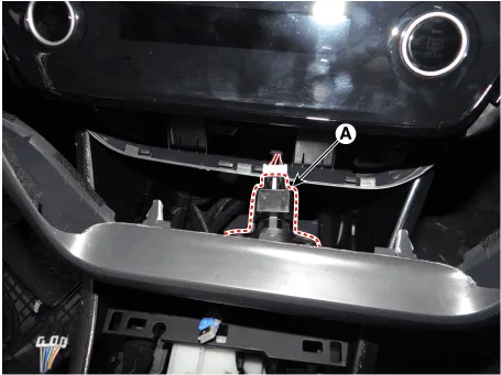
| 5. | Press the lock pin and separate the in-car sensor connector (A).
|
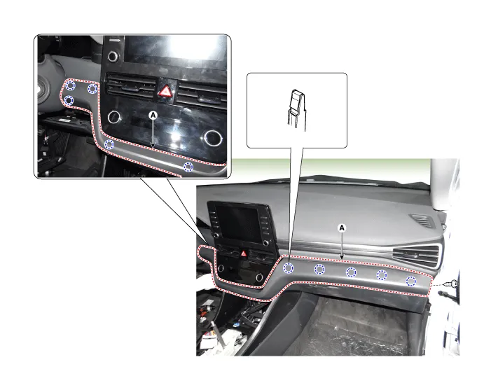
| 6. | Loosen the mounting screws, nuts and remove the glove box upper cover assembly (A).
|

| 7. | To install, reverse the removal procedure.
|

Component Location 1. Glove box upper cover assembly
Component Location 1. Main crash pad assembly
Other information:
Hyundai Ioniq (AE) 2017-2022 Service & Repair Manual: Description and operation
System OverviewParking Distance Warning (PDW) is an electronic driving aid that warns the driver to be cautious while parking or driving at low speed. The sensor uses ultrasonic waves to detect objects within proximity of the vehicle.PDW consists of four RPS sensors which are detecting the obstacles and transmit the result separated into three war
Hyundai Ioniq (AE) 2017-2022 Service & Repair Manual: Parking Distance Warning (PDW) ON/OFF Switch. Repair procedures
Removal • Put on gloves to prevent hand injuries. • When removing with a flat-tip screwdriver or remover, wrap protective tape around the tools to prevent damage to components.
Categories
- Manuals Home
- Hyundai Ioniq Owners Manual
- Hyundai Ioniq Service Manual
- Engine Control/Fuel System
- If the 12 Volt Battery is Discharged (Hybrid Vehicle)
- Jump Starting
- New on site
- Most important about car

Copyright © 2026 www.hioniqae.com - 0.0139