Hyundai Ioniq (AE): Hybrid Control System / HPCU (Hybrid Power Control Unit). Repair procedures
| Removal |
|

| 1. | Shut off the high voltage circuit. (Refer to Hybrid Control System - "High Voltage Shutoff Procedure") |
| 2. | Remove the air cleaner assembly and air duct. (Refer to Engine Mechanical System - "Air Cleaner") |
| 3. | Remove the ECM & TCM bracket assembly. (Refer to Engine Control/Fuel System - "Engine Control Module") |
| 4. | Drain the coolant of hybrid motor cooling system. (Refer to Hybrid Motor Cooling System - "Coolant") |
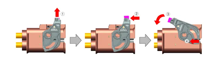
| 5. | Disconnect the motor power cable connector (A) and HSG power cable connector (B) after loosening the mounting bolts.
|
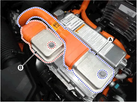
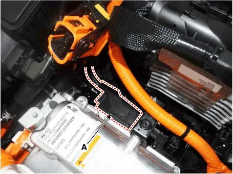
| 6. | Disconnect the power cable (A) and inverter power cable (B) from the HPCU.
|

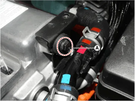
| 7. | Disconnect the HCU & inverter (MCU) connector (A).
|
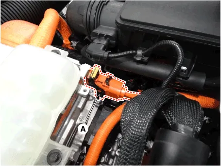
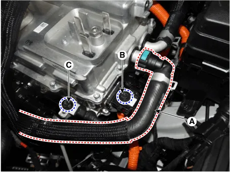
| 8. | Disconnect the coolant outlet hose & pipe after loosening the mounting bolt (A).
|
| 9. | Disconnect the coolant inlet hose quick-connector (A). |
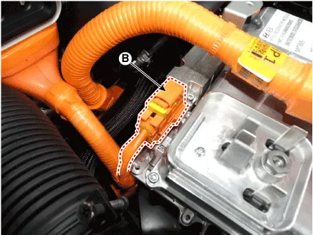
| 10. | Remove the LDC power outlet cable mounting bolt (B) and ground cable bolt (C).
|
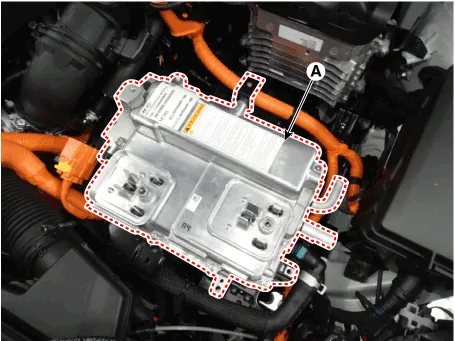
| 11. | Remove the HPCU (A) after loosening the mounting bolts.
|
| Installation |
|
| 1. | Install the HPCU in the reverse order of removal.
|
| 2. | Refill the hybrid motor cooling system coolant and perform air bleeding by using the GDS. (Refer to Hybrid Motor Cooling System - "Coolant")
|

| 1. | Turn the ignition switch OFF. |
| 2. | Connect the KDS / GDS to Data Link Connector (DLC). Turn the ignition switch ON. |
| 3. | Select "Vehicle, Model year, Engine, System". |
| 4. | Select "Vehicle S/W Management". |
| 5. | Select "HCU Variant Coding".
|

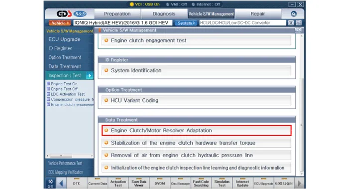
| 1. | Turn the ignition switch OFF. |
| 2. | Connect the KDS / GDS to Data Link Connector (DLC). Turn the ignition switch ON. |
| 3. | Select "Vehicle, Model year, Engine, System". |
| 4. | Select "Vehicle S/W Management". |
| 5. | Select "Engine clutch/motor resolver adaptation.".
|
Components1. Hybrid Control Unit (HCU)2. Inverter3. Low DC/DC Converter (LDC)4. Connector (↔ High Voltage Battery)5. Connector (↔ Motor)6. Connector (↔ HSG)7.
HCU Terminal and Input / Output SignalTerminal FunctionConnector [C133-S] Pin No Description Connected to 1HCU GroundChassis ground2HCU GroundChassis ground3HCU GroundChassis ground4Battery power (B+)Battery5Battery power (B+)Battery6Battery power (B+)Battery7- 8- 9- 10- 11- 12- 13- 14- 15Brake Switch 2 signal inputBrake Switch (NC, IG1)16Brake Switch 1 signal inputBrake Switch (NO, B+)17- 18- 19- 20- 21- 22- 23- 24- 25- 26- 27- 28- 29- 30- 31-32-33-34- 35- 36- 37- 38Start signal inputSmart Key Unit39- 40- 41- 42- 43- 44- 45- 46- 47- 48- 49- 50- 51- 52- 53- 54- 55- 56- 57- 58- 59- 60- 61- 62- 63- 64- 65- 66- 67- 68- 69- 70- 71- 72- 73IGN signal inputSmart Key Unit74- 75- 76- 77- 78Powertrain CAN [High] signal inputOther control modules79Powertrain CAN [Low] signal inputOther control modules80- 81Hybrid CAN [High] signal inputOther control modules82Hybrid CAN [Low] signal inputOther control modules83- 84- 85- 86- 87- 88- 89- 90- 91- 92- 93- 94- Input/Output signalConnector [C133-S] Pin no Description Condition Type Level 1HCU GroundAlwaysDC VoltageMax.
Other information:
Hyundai Ioniq (AE) 2017-2022 Service & Repair Manual: PTC Heater. Description and operation
DescriptionThe PTC (Positive Temperature Coefficient) heater is installed at the exit or the backside of the heater core.The PTC heater is an electric heater using a PTC element as an auxiliary heating device that supplements deficiency of interior heat source in highly effective hybrid engine.
Hyundai Ioniq (AE) 2017-2022 Service & Repair Manual: Front Radar Unit. Description and operation
DescriptionThe smart cruise control unit is installed on the front right side of the chassis. A radar sensor is embedded in the front section of the unit. This sensor detects vehicles and objects in front of the vehicle. The radar sensor can detect up to 64 objects ahead of a vehicle.
Categories
- Manuals Home
- Hyundai Ioniq Owners Manual
- Hyundai Ioniq Service Manual
- Jump starting procedure
- How to Connect Portable Charger (ICCB: In-Cable Control Box)
- Brake System
- New on site
- Most important about car
