Hyundai Ioniq (AE): High Voltage Battery Control System / Main Relay. Repair procedures
Hyundai Ioniq (AE) 2017-2022 Service & Repair Manual / Hybrid Control System / High Voltage Battery Control System / Main Relay. Repair procedures
| Removal |
|

| 1. | Shut off the high voltage. (Refer to Hybrid Control System - "High Voltage Shut-off Procedures") |
| 2. | Remove the rear seat cushion. (Refer to Body - "Rear Seat Assembly") |
| 3. | Remove the rear door scuff trim. (Refer to Body - "Door Scuff Trim") |
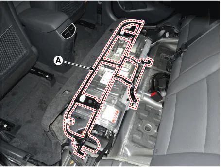
| 4. | Remove the upper frame (A) after loosening the mounting bolts and nuts.
|
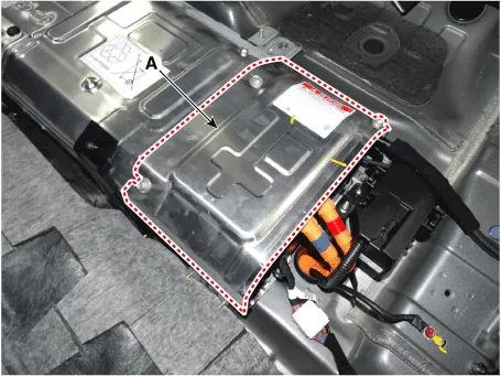
| 5. | Remove the high voltage battery rear cover (A) after loosening the mounting bolts and nuts.
|
| 6. | Remove the inlet cooling duct. (Refer to Hybrid Control System - "Cooling Duct") |
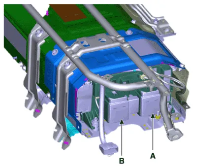
| 7. | Disconnect the main relay (+) (A), and main relay (-) (B).
|
| Installation |
|
| 1. | Install the main relay in the reverse order of removal.
|
| Inspection |
|
Checking for Welding in the High Voltage Main Relay
| [Using GDS service data to check for main relay weld damage] |
| 1. | Connect the GDS to the Data Link Connector (DLC). |
| 2. | Turn the ignition switch ON. |
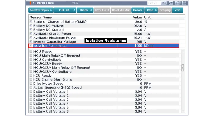
| 3. | Check the BMS weld damage state in the GDS service data.
|
| [Using a Multimeter to measure weld damage] |
| 1. | Shut off the high voltage. (Refer to Hybrid Control System - "High Voltage Shut-off Procedures") |
| 2. | Remove the high voltage battery rear cover. (Refer to High Voltage Battery System - "Case") |
| 3. | Remove the inlet cooling duct. (Refer to Hybrid Control System - "Cooling Duct") |
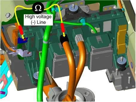
| 4. | Measure the high voltage main relay resistance and check for signs of weld damage.
|
High voltage main relay (-) switch resistance
| 1. | Shut off the high voltage. (Refer to Hybrid Control System - "High Voltage Shut-off Procedures") |
| 2. | Remove the high voltage battery rear cover. (Refer to High Voltage Battery System - "Case") |
| 3. | Remove the inlet cooling duct. (Refer to Hybrid Control System - "Cooling Duct") |
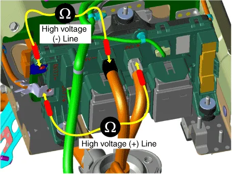
| 4. | Measure the resistance between the high voltage power terminal (-) and the inverter power terminal (-).
|
| [Circuit inspection (Relay ON)] |
|

| 1. | Connect the GDS to the Data Link Connector (DLC). |
| 2. | Turn the ignition switch ON. |
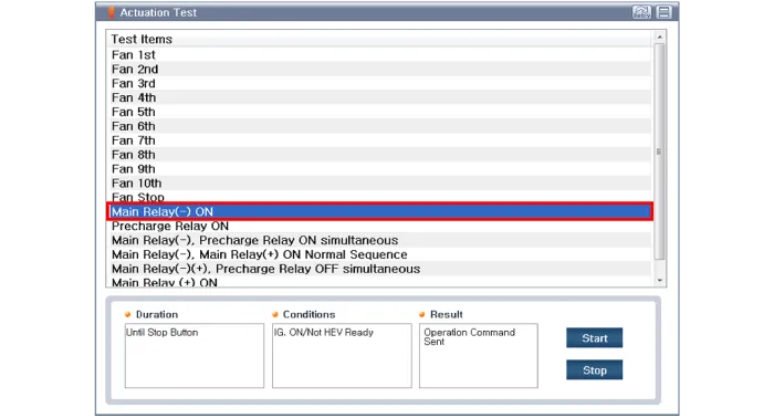
| 3. | Activate the main relay by using "Actuation Test" on the GDS as shown in the illustration below.
|
High Voltage Main Relay Coil Resistance
| 1. | Shut off the high voltage. (Refer to Hybrid Control System - "High Voltage Shut-off Procedures") |
| 2. | Remove the power relay assembly. (Refer to High Battery System - "Power Relay Assembly") |
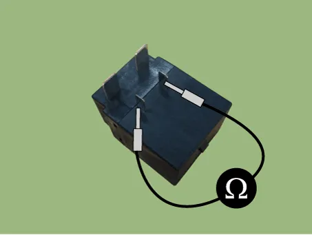
| 3. | Check for continuity between the terminals using an ohmmeter.
|
Circuit Diagram
DescriptionThe Power Relay Assembly (PRA) consists of the positive and negative main relays, pre-charge relay, pre-charge resistor and battery current sensor.
Other information:
Hyundai Ioniq (AE) 2017-2022 Service & Repair Manual: Cruise Control Switch. Components and components location
C
Hyundai Ioniq (AE) 2017-2022 Service & Repair Manual: Cruise Control Switch. Repair procedures
Removal1.Disconnect the negative (-) battery terminal.2.Remove the steering wheel assembly.(Refer to Steering System - "Steering Wheel")3.Remove the steering back cover (A).4.Remove the steering remote control connector (A).5.Remove the steering remote control after loosening the screws.
Categories
- Manuals Home
- Hyundai Ioniq Owners Manual
- Hyundai Ioniq Service Manual
- Hybrid Control System
- How to Connect Portable Charger (ICCB: In-Cable Control Box)
- Jump Starting
- New on site
- Most important about car

Copyright © 2026 www.hioniqae.com - 0.0253