Hyundai Ioniq (AE): Motor Driven Power Steering / MDPS Control Unit. Repair procedures
| •
| If a DTC occurs in the ECU, check the connectors and wiring. If no problem is found, replace the ECU. |
|
| •
| Before replacing the MDPS ECU, use the diagnostic device to read the settings of the old ECU |
|
| 1. | Perform the "ECU data backup" by GDS following in the order below. | (1) | Connect self-diagnosis connector(16pins) located in the lower of driver side crash pad to self-diagnosis device. |
| (2) | Turn the self-diagnosis device after key is ON. |
| (3) | After Selecting the "vehicle model" and "EPS system" on GDS vehicle selection screen. |
| (4) | Select the "Part exchange(Power steering ECU)" 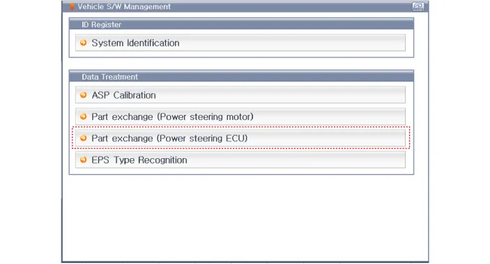
|
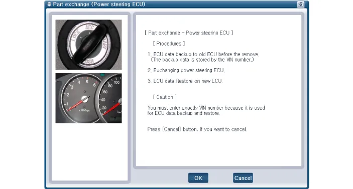
| (5) | Follow the instructions shown on the screen. 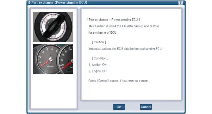
|
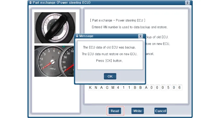
| (6) | Insert the VIN number and then select the "Read" in order to the ECU information save. 
|
|
| 2. | Disconnect the battery negative cable from the battery and then wait for at least 30 seconds. |
| 3. | Remove the crash pad lower panel. (Refer to Body - "Crash Pad Lower Panel") |
| 4. | Remove the knee airbag (KAB) module. (Refer to Restraint - "Knee Airbag (KAB) Module") |
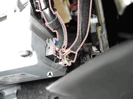
| 5. | Disconnect the connector from the MDPS control unit. 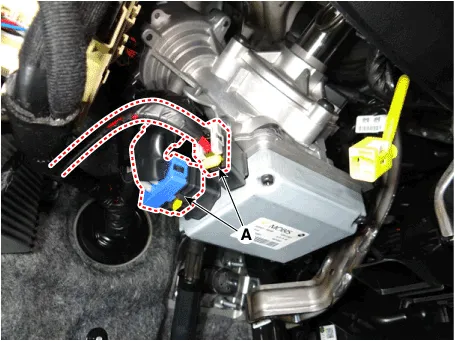
|
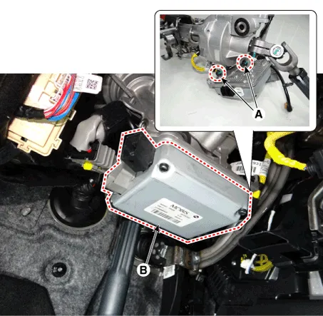
| 6. | Loosen the mounting bolts (A) and then remove the MDPS ECU (B). Tightening torque : 19.6 - 23.5 N·m (2.0 - 2.4 kgf·m, 14.5 - 17.4 lb·ft) |
|
| 7. | Perform the "ECU data restore" by GDS following in the order below. | (1) | Connect self-diagnosis connector(16pins) located in the lower of driver side crash pad to self-diagnosis device. |
| (2) | Turn the self-diagnosis device after key is ON. |
| (3) | After Selecting the "vehicle model" and "EPS system" on GDS vehicle selection screen. |
| (4) | Select the "Part exchange(Power steering ECU)"
|
| (5) | Follow the instructions shown on the screen.
|
| (6) | Insert the VIN number and then select the "Write" in order to the ECU information save. 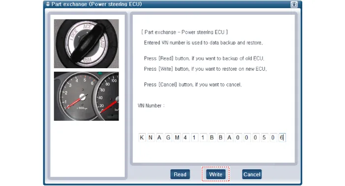
|
|
| 8. | Conduct the "ASP Calibration" by GDS. (Refer to MDPS Control Unit- "Diagnosis with GDS") |
| 9. | Remove the DTC and then perform the Conduct the "MDPS TEST (Motor Driven Power Steering)" by GDS. (Refer to Motor Driven Power Steering - "MDPS Performance Inspection") |
| 10. | Turn off the IGN switch and wait for 10 seconds or more. Then check the operation after starting the engine. |
| –
| Steering-angle sensor detects the steering angle and steering angle speed. Steering angle and steering angle speed are used for steering wheel damping and return controls in addition to providing assistance torque. |
| •
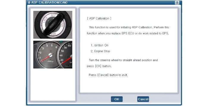
| You can use a scan tool to(GDS) check if the battery voltage is proper before perform the "ASP Calibration". |
| •
| Make sure that no connector engaged to the vehicle or scan tool is disconnected during the "ASP Calibration". |
| •
| Once the "ASP Calibration" is complete, turn off the IG switch and wait for 10 seconds or more before starting the engine to check the operation. |
|
ASP Calibration procedures
| 1. | Connect self-diagnosis connector(16pins) located in the lower of driver side crash pad to self-diagnosis device. |
| 2. | Turn the self-diagnosis device after key is ON. |
| 3. | Turn the steering wheel to straight ahead position. |
| 4. | After Selecting the "vehicle model" and "system", select the "ASP Calibration" on GDS vehicle selection screen. 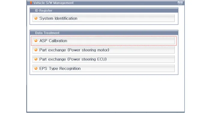
|
| 6. | Turn off the IG switch and wait for 10 seconds or more before starting the engine. And then make sure that MDPS works properly. |
Replacement
•
When a DTC related to MDPS motor occurs, check the connectors and wiring. If no problem is found, replace the motor.
Removal1.Remove the MDPS assembly.(Refer to Steering System - "MDPS Assembly")2.Remove the MDPS control unit.(Refer to Steering System - "MDPS Control Unit")3.
Other information:
Removal1.Disconnect the negative (-) battery terminal.2.Remove the front / rear bumper cover.(Refer to Body - "Front Bumper Cover")(Refer to Body - "Rear Bumper Cover")3.Disconnect the connector (A) from the parking assist sensor.4.Remove the sensor (A) by pulling out both ends of the sensor holder.
C


