Hyundai Ioniq (AE): Hybrid Motor Control System / Motor Control Unit(MCU). Schematic diagrams
Hyundai Ioniq (AE) 2017-2022 Service & Repair Manual / Hybrid Motor System / Hybrid Motor Control System / Motor Control Unit(MCU). Schematic diagrams
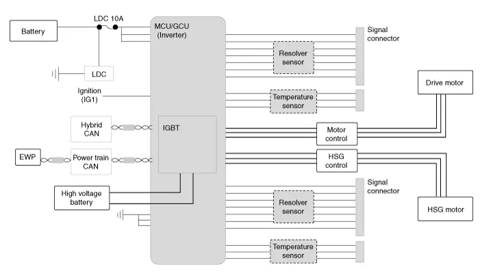
| Diagram System Circuit |
A high-capacity power module is applied to the two high-voltage motors.
The power module consists of a high - speed switching circuit that is isolated from the IGBT and DIODE circuits.
The capacity of the high-voltage battery is approx. 270V. But the power module needs to use a voltage of maximum 650V to ensure stability and reliability.
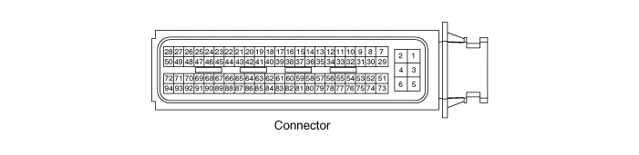
| MCU terminal input/output signal connector |
| Functions of MCU Terminal |
Connector (94 pins)
|
Terminal
|
Signal
|
Usage
|
| 5 | VB1 | Constant power (B+) |
| 6 | VB2 | Constant power (B+) |
| 3 | GND1 | Power ground |
| 4 | VB3 | Constant power (B+) |
| 1 | GND2 | Power ground |
| 2 | GND3 | Power ground |
| 73 | IGN | Ignition |
| 74 | - | |
| 75 | L_CAN_H | C_CAN_[High] |
| 76 | L_CAN_L | C_CAN_[Low] |
| 77 | - | |
| 78 | P_CAN_H | P - CAN [High] |
| 79 | P_CAN_L | P - CAN [Low] |
| 80 | - | |
| 81 | H_CAN_H | H - CAN [High] |
| 82 | H_CAN_L | H - CAN [Low] |
| 83 | - | |
| 84 | - | |
| 85 | - | |
| 86 | - | |
| 87 | H_REZ+ | HSG resolver (+) power |
| 88 | H_REZ- | HSG resolver (-) power |
| 89 | - | |
| 90 | - | |
| 91 | - | |
| 92 | - | |
| 93 | M_REZ+ | Motor resolver (+) power |
| 94 | M_REZ- | Motor resolver (-) power |
| 51 | - | |
| 52 | - | |
| 53 | - | |
| 54 | - | |
| 55 | - | |
| 56 | - | |
| 57 | - | |
| 58 | - | |
| 59 | - | |
| 60 | - | |
| 61 | - | |
| 62 | H_REZS1 | HSG resolver sensor (S1) input signal |
| 63 | H_REZS3 | HSG resolver sensor (S3) input signal |
| 64 | H_REZS2 | HSG resolver sensor (S2) input signal |
| 65 | H_REZS4 | HSG resolver sensor (S4) input signal |
| 66 | H_REZ_S | SHEILD |
| 67 | - | |
| 68 | M_REZS1 | Motor resolver sensor (S1) input signal |
| 69 | M_REZS3 | Motor resolver sensor (S3) input signal |
| 70 | M_REZS2 | Motor resolver sensor (S2) input signal |
| 71 | M_REZS4 | Motor resolver sensor (S4) input signal |
| 72 | M_REZ_S | SHEILD |
| 29 | - | |
| 30 | - | |
| 31 | ||
| 32 | ||
| 33 | ||
| 34 | ||
| 35 | - | |
| 36 | ||
| 37 | ||
| 38 | START_SIGNAL | Start signal input signal |
| 39 | - | |
| 40 | - | |
| 41 | - | |
| 42 | HSG_TM_GND | Sensor ground |
| 43 | HSG_TM | HSG temperature sensor input signal |
| 44 | HSG_TM_S | SHEILD |
| 45 | - | |
| 46 | - | |
| 47 | - | |
| 48 | MOT_TM_GND | Sensor ground |
| 49 | MOT_TM | Motor temperature sensor input signal |
| 50 | MOT_TM_S | SHEILD |
| 7 | - | |
| 8 | - | |
| 9 | - | |
| 10 | - | |
| 11 | - | |
| 12 | - | |
| 13 | - | |
| 14 | - | |
| 15 | BRAKE_SW2 | Brake switch 2 input signal (NC, IG1) |
| 16 | BRAKE_SW1 | Brake switch 1 input signal (NO, B+) |
| 17 | ||
| 18 | ||
| 19 | ||
| 20 | ||
| 21 | ||
| 22 | ||
| 23 | ||
| 24 | ||
| 25 | ||
| 26 | ||
| 27 | ||
| 28 |
| MCU terminal input/output signal |
|
Terminal
|
Signal
|
Usage
|
Condition
|
Type
|
Level
|
Waveform
|
| 5 | VB1 | Constant power (B+) | Constant | DC Voltage | Battery Power |   |
| 6 | VB2 | Constant power (B+) | Constant | DC Voltage | Battery Power |   |
| 3 | GND1 | Power ground | Constant | DC Voltage | Max. 50 mV | |
| 4 | VB3 | Constant power (B+) | Constant | DC Voltage | Battery Power | |
| 1 | GND2 | Power ground | Constant | DC Voltage | Max. 50 mV | |
| 2 | GND3 | Power ground | Constant | DC Voltage | Max. 50 mV |   |
| 73 | IGN | Ignition | IG ON | DC Voltage | Battery Power |   |
| 74 | - | |||||
| 75 | L_CAN_H | C - CAN [High] | IG ON | Pulse | Dominant : 2.75 - 4.5 (3.5) V Recessive : 2.0 - 3.0 (2.5) V |
|
| 76 | L_CAN_L | C - CAN [Low] | IG ON | Pulse | Recessive : 2.0 - 3.0 (2.5) V Dominant : 0.5 - 2.25 (1.5) V | |
| 77 | - | |||||
| 78 | P_CAN_H | P - CAN [High] | IG ON | Pulse | Dominant : 2.75 - 4.5 (3.5) V Recessive : 2.0 - 3.0 (2.5) V |
|
| 79 | P_CAN_L | P - CAN [Low] | IG ON | Pulse | Recessive : 2.0 - 3.0 (2.5) V Dominant : 0.5 - 2.25 (1.5) V | |
| 80 | - |   |   |   |   | |
| 81 | H_CAN_H | H - CAN [High] | IG ON | Pulse | Dominant : 2.75 - 4.5 (3.5) V Recessive : 2.0 - 3.0 (2.5) V |
|
| 82 | H_CAN_L | H - CAN [Low] | IG ON | Pulse | Recessive : 2.0 - 3.0 (2.5) V Dominant : 0.5 - 2.25 (1.5) V | |
| 83 | - |   | ||||
| 84 | - |   | ||||
| 85 | - | |||||
| 86 | - | |||||
| 87 | H_REZ+ | HSG resolver (+) power | IG ON | Differential, Analog | 14 Vpp sine wave |
|
| 88 | H_REZ- | HSG resolver (-) power | ||||
| 89 | - |   |   |   |   | |
| 90 | - | |||||
| 91 | - |   | ||||
| 92 | - |   | ||||
| 93 | M_REZ+ | Motor resolver (+) power | IG ON | Differential, Analog | 14 Vpp sine wave |
|
| 94 | M_REZ- | Motor resolver (-) power | ||||
| 51 | - |   |   |   |   | |
| 52 | - |   |   |   |   | |
| 53 | - |   |   |   |   | |
| 54 | - | |||||
| 55 | - |   | ||||
| 56 | - |   | ||||
| 57 | - |   | ||||
| 58 | - |   | ||||
| 59 | - |   | ||||
| 60 | - |   | ||||
| 61 | - |   |   |   |   | |
| 62 | H_REZS1 | HSG resolver sensor (S1) input signal | IG ON | Differential, Analog | 0 - 3 Vpp sine wave |
|
| 63 | H_REZS3 | HSG resolver sensor (S3) input signal | ||||
| 64 | H_REZS2 | HSG resolver sensor (S2) input signal | IG ON | Differential, Analog | 0 - 3 Vpp sine wave |
|
| 65 | H_REZS4 | HSG resolver sensor (S4) input signal | ||||
| 66 | H_REZ_S | SHEILD | Constant | DC Voltage | Max. 50 mV | |
| 67 | - | |||||
| 68 | M_REZS1 | Motor resolver sensor (S1) input signal | IG ON | Differential, Analog | 0 - 3 Vpp sine wave |
|
| 69 | M_REZS3 | Motor resolver sensor (S3) input signal | ||||
| 70 | M_REZS2 | Motor resolver sensor (S2) input signal | IG ON | Differential, Analog | 0 - 3 Vpp sine wave |
|
| 71 | M_REZS4 | Motor resolver sensor (S4) input signal | ||||
| 72 | M_REZ_S | SHEILD | Constant | DC Voltage | Max. 50 mV | |
| 29 | - | |||||
| 30 | - | |||||
| 31 | ||||||
| 32 | ||||||
| 33 | ||||||
| 34 | ||||||
| 35 | - | |||||
| 36 | ||||||
| 37 | ||||||
| 38 | START_SIGNAL | Start signal input signal | IG ST | DC Voltage | Battery voltage | |
| 39 | - | |||||
| 40 | - | |||||
| 41 | - | |||||
| 42 | HSG_TM_GND | Sensor ground | Constant | DC Voltage | Max. 50 mV | |
| 43 | HSG_TM | HSG temperature sensor input signal | IG ON | Analog | 0 - 5V | |
| 44 | HSG_TM_S | SHEILD | Constant | DC Voltage | Max. 50 mV | |
| 45 | - | |||||
| 46 | - | |||||
| 47 | - | |||||
| 48 | MOT_TM_GND | Sensor ground | Constant | DC Voltage | Max. 50 mV | |
| 49 | MOT_TM | Motor temperature sensor input signal | IG ON | Analog | 0 - 5V | |
| 50 | MOT_TM_S | SHEILD | Constant | DC Voltage | Max. 50 mV | |
| 7 | - | |||||
| 8 | - | |||||
| 9 | - | |||||
| 10 | - | |||||
| 11 | - | |||||
| 12 | - | |||||
| 13 | - | |||||
| 14 | - | |||||
| 15 | BRAKE_SW2 | Brake switch 2 input signal (NC, IG1) | IG ON | DC Voltage | Battery voltage | |
| 16 | BRAKE_SW1 | Brake switch 1 input signal (NO, B+) | Constant | DC Voltage | Battery voltage | |
| 17 | ||||||
| 18 | ||||||
| 19 | ||||||
| 20 | ||||||
| 21 | ||||||
| 22 | ||||||
| 23 | ||||||
| 24 | ||||||
| 25 | ||||||
| 26 | ||||||
| 27 | ||||||
| 28 |


Component location1. HPCU (Hybrid Power Control Unit)(LDC+MCU+HCU+Reservoir)2. Hybrid drive motor3. Hybrid starter generator (HSG)4. Electrical radiator5.
Removal • MCU is integrated with HPCU. Therefore, to install / remove the MCU, follow the procedure for installing / removing the HPCU.
Categories
- Manuals Home
- Hyundai Ioniq Owners Manual
- Hyundai Ioniq Service Manual
- Repair procedures
- General Information
- If the 12 Volt Battery is Discharged (Hybrid Vehicle)
- New on site
- Most important about car

Copyright © 2026 www.hioniqae.com - 0.0149