
Hyundai Ioniq (AE): Lubrication System / Oil Pressure Switch. Repair procedures
| Removal and Installation |
| 1. | Disconnect the battery negative terminal. |
| 2. | Remove the engine room under cover. (Refer to Engine and Transaxle Assembly - "Engine Room Under Cover") |
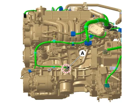
| 3. | Disconnect the oil pressure switch connector (A).
|
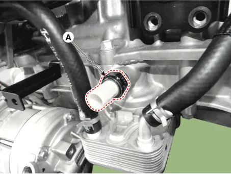
| 4. | Remove the oil pressure switch (A).
|
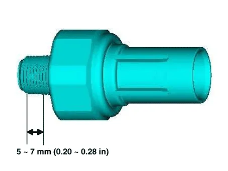
| 5. | Install in the reverse order of removal.
|

| Inspection |
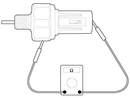
| 1. | Check the continuity between the terminal and the body with an ohmmeter. If there is no continuity, replace the oil pressure switch.
|
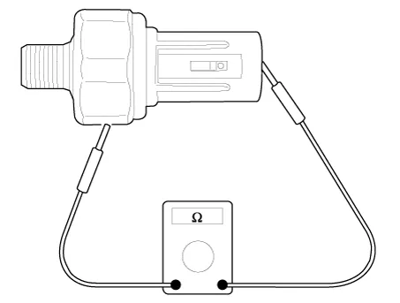
| 2. | Check the continuity between the terminal and the body when the fine wire is pushed. If there is continuity even when the fine wire is pushed, replace the switch. |
| 3. | If there is no continuity when a 50 kPa (0.50 kgf/cm², 7.25 psi) is applied through the oil hole, the switch is operaing properly. Check for air leakage. If air leaks, the diaphragm is broken. Replace it.
|
Removal and installation1.Remove the timing chain cover.(Refer to Timing System - "Timing Chain Cover")2.Remove the oil pump cover (A). Tightening torque : Screws :5.
Components1. Oil pan2. Oil screen3. Gasket4. Drain plug5. Drain plug gasket
Other information:
Hyundai Ioniq (AE) 2017-2022 Service & Repair Manual: emperature Control Actuator. Description and operation
DescriptionThe temperature control actuator is located at the heater unit. It regulates the temperature by the procedure as follows. The signal from the control unit adjusts the position of the temperature door by operating the temperature switch. Then the temperature will be regulated by the hot/cold air ratio decided by the position of the temper
Hyundai Ioniq (AE) 2017-2022 Service & Repair Manual: Auto Defoging Actuator. Repair procedures
Inspection1.Turn the ignition switch OFF. 2.Disconnect the auto defogging connector. 3.Verify that the auto defogging actuator operates to the open position when connecting 12V to terminal 3 and grounding terminal 4. Verify that the auto defogging actuator operates to the close position when connected in reverse.
Categories
- Manuals Home
- Hyundai Ioniq Owners Manual
- Hyundai Ioniq Service Manual
- Hybrid Vehicle Engine Compartment
- Maintenance
- If the 12 Volt Battery is Discharged (Hybrid Vehicle)
- New on site
- Most important about car
