Hyundai Ioniq: Cylinder Block / Piston and Connecting Rod. Repair procedures
| •
| Be sure to read and follow the "General Safety Information and Caution" before doing any work related with the high voltage system. Failure to follow the safety instructions may result in serious electrical injuries. |
| •
| Be sure to read and follow the "High Voltage Shut-off Procedures" before doing any work related with the high voltage system. Failure to follow the safety instructions may result in serious electrical injuries. |
|
| •
| Use fender covers to avoid damaging painted surfaces. |
| •
| To avoid damaging the cylinder head, wait until the engine coolant temperature drops below normal temperature (20°C [68°F]) before removing it. |
| •
| When handling a metal gasket, take care not to fold the gasket or damage the contact surface of the gasket. |
| •
| To avoid damage, unplug the wiring connectors carefully while holding the connector portion. |
|
| •
| Mark all wiring and hoses to avoid misconnection. |
| •
| Turn the crankshaft damper pulley so that the No.1 piston is at top dead center. |
|
| 1. | Remove the engine assembly from the vehicle. (Refer to Engine and Transaxle Assembly - "Engine and Transaxle Assembly") |
| 2. | Remove the transaxle assembly from the engine assembly. (Refer to Double Clutch Transmission (DCT) System - "Double Clutch Transmission (DCT)") |
| 3. | Remove the flywheel. (Refer to Cylinder Block - "Flywheel") |
| 4. | Remove the rear oil seal. (Refer to Cylinder Block - "Rear Oil Seal") |
| 5. | Install the engine to engine stand for disassembly. |
| 6. | Remove the intake manifold. (Refer to Intake and Exhaust System - "Intake Manifold") |
| 7. | Remove the exhaust manifold. (Refer to Intake and Exhaust System - "Exhayst Manifold") |
| 8. | Remove the hybrid starter generator (HSG). (Refer to Hybrid Motor System - "Hybrid Starter Generator (HSG)") |
| 9. | Remove the timing chain. (Refer to Timing System - "Timing Chain") |
| 10. | Remove the cylinder head assembly. (Refer to Cylinder Head Assembly - "Cylinder Head") |
| 11. | Remove the thermostat. (Refer to Cooling System - "Thermostat") |
| 12. | Remove the EGR cooler. (Refer to Intake and Exhaust System - "EGR Cooler") |
| 13. | Remove the A/C compressor. (Refer to Heating, Ventilation Air conditioning -"Compressor") |
| 14. | Remove the knock sensor. (Refer to Engine Control / Fuel System - "Knock Sensor") |
| 15. | Remove the oil pan and oil screen. (Refer to Lubrication System - "Oil Pan") |
| 16. | Remove the ladder frame (A). 
| •
| Insert the blade of SST (09215-3C000) between the cylinder block and the ladder frame and cut out applied sealer. Then, remove the ladder frame. |
|
| •
| Insert the SST between the cylinder block and the ladder frame by tapping it with a plastic hammer in the direction of (1) arrow. |
| •
| After tapping the SST with a plastic hammer along the direction of (2) arrow around more than 2/3 edge of the ladder frame, remove it from the cylinder block. |
| •
| Do not turn over the SST abruptly without tapping as it may damage the SST. |
| •
| Be careful not to damage the contacting surfaces of cylinder block and ladder frame. |
|
|
| 17. | Check the connecting rod side clearance. |
| 18. | Check the connecting rod cap oil clearance. |
| 19. | Remove the piston and connecting rod assemblies. | (1) | Using a ridge reamer, remove all the carbon from the top of the cylinder. |
| (2) | Remove the connecting rod bearing cap (A). |
| (3) | Push the piston, connecting rod assembly (B) and upper bearing through the top of the cylinder block. 
| •
| Mark the connecting rod, and caps to be able to reassemble in the original position and direction. |
|
| •
| Keep the bearings, connecting rod and cap together. |
| •
| Arrange the piston and connecting rod assemblies in the correct order. |
| •
| Mark the piston and connecting rod assemblies to be able to reassemble in the original position. |
|
|
|
| 20. | Check fit between piston and piston pin. Try to move the piston back and forth on the piston pin. If any movement is felt, replace piston and piston pin as a set. |
| 21. | Remove the piston rings. | (1) | Using a piston ring expander, remove the 2 compression rings. |
| (2) | Remove the 2 side rails and oil ring spacer by hand. | •
| Arrange the piston rings in the correct order only. |
|
|
|
| 22. | Remove the connecting rod from the piston. Using a press, remove the piston pin from the piston. |
Connecting Rod
| 1. | Check the connecting rod side clearance. Using a feeler gauge, measure the end play while moving the connecting rod back and forth. Standard : 0.10 - 0.25mm (0.0039 - 0.0098in) |
| •
| If out-of-tolerance, install a new connecting rod. |
| •
| If still out-of-tolerance, replace the crankshaft. |
|
| 2. | Check the connecting rod bearing oil clearance. | (1) | Check the match marks on the connecting rod and cap are aligned to ensure correct reassembly. |
| (2) | Remove the 2 connecting rod cap bolts. |
| (3) | Remove the connecting rod cap and lower bearing. |
| (4) | Clean the crank pin journal and bearing. |
| (5) | Place a plastigage across the crankshaft pin journal. |
| (6) | Reinstall the lower bearing and cap, and tighten the bolts. Tightening torque : 11.0 - 15.0 N.m (1.1 - 1.5 kgf.m, 8.0 - 10.8 lb-ft) + 88 - 92° |
| •
| Do not turn the crankshaft. |
|
|
| (7) | Remove the 2 bolts, connecting rod cap and lower bearing. |
| (8) | Measure the plastigage at its widest point. Standard oil clearance : 0.018 - 0.036mm (0.0007 - 0.0014in) Limit oil clearance : 0.030 - 0.056mm (0.0012 - 0.0022in) |
|
| (9) | If the plastigage measures too wide or too narrow, remove the upper and lower bearing and then install a new bearings with the same color mark (Refer to connecting rod bearing selection table) Recheck the oil clearance. | •
| Do not file, shim, or scrape the bearings or the caps to adjust clearance. |
|
|
| (10) | If the plastigage shows the clearance is still incorrect, try the next lager or smaller bearing. (Refer to connecting rod bearing selection table Recheck the oil clearance. | •
| If the proper clearance cannot be obtained by using the appropriate lager or smaller bearings, replace the crankshaft and start over. |
|
| •
| If the alignment marks are unreadable because of an accumulation of grease or grime, don't clean with a wire or abrasive cleaner. Clean only with correct cleaning solvent or detergent. |
|
Connecting Rod Mark Location 
Discrimination of Connecting Rod
Grade
| Mark
| Connecting Rod Big-end Inner Diameter
| 0
| A
| 42.000 - 42.006mm
(1.6535 - 1.6540in)
| 1
| B
| 42.006 - 42.012mm
(1.6537 - 1.6540in)
| 2
| C
| 42.012 - 42.018mm
(1.6540 - 1.6542in)
|
Crankshaft Pin Journal Mark Location 
Discrimination of Crankshaft Pin Journal
Class
| Mark
| Crankshaft Pin Journal outer Diameter
| I
| 1
| 38.966 - 38.972 mm
(1.5340 - 1.5343 in)
| II
| 2
| 38.960 - 38.966 mm
(1.5338 - 1.5340 in)
| III
| 3
| 38.954 - 38.960 mm
(1.7698 - 1.7701 in)
|
Connecting Rod Bearing Mark Location 
Discrimination of Connecting Rod Bearing
Grade
| Color
| Connecting Rod Bearing Thickness
| A
| Blue
| 1.514 - 1.517 mm
(0.0596 - 0.0597 in)
| B
| Black
| 1.511 - 1.514 mm
(0.0595 - 0.0596 in)
| C
| None
| 1.508 - 1.511 mm
(0.0594 - 0.0595 in)
| D
| Green
| 1.505 - 1.508mm
(0.0593 - 0.0594 in)
| E
| Yellow
| 1.502 - 1.505 mm
(0.0591 - 0.0593 in)
|
|
| (11) | Select the bearing by using selection table. Connecting Rod Bearing Selection Table
Connecting Rod Bearing
| Connecting Rod Mark
| 0(A)
| 1(B)
| 2(C)
| Crank shaft pin journal mark
| I (1)
| E(Yellow)
| D(Green)
| C(None)
| II (2)
| D (Green)
| C(None)
| B(Black)
| III (3)
| C (None)
| B(Black)
| A(Blue)
|
|
|
| 3. | Check the connecting rods. | (1) | When reinstalling, make sure that cylinder numbers put on the connecting rod and cap at disassembly match. When a new connecting rod is installed, make sure that the notches for holding the bearing in place are on the same side. |
| (2) | Replace the connecting rod if it is damaged on the thrust faces at either end. Also if step wear or a severely rough surface of the inside diameter of the small end is apparent, the rod must be replaced as well. |
| (3) | Using a connecting rod aligning tool, check the rod for bend and twist. If the measured value is close to the repair limit, correct the rod by a press. Any connecting rod that has been severely bent or distorted should be replaced. Allowable bend of connecting rod : 0.05 mm (0.0020 in.) or less for 100 mm (3.94 in.) Allowable twist of connecting rod : 0.10 mm (0.0039 in.) or less for 100 mm (3.94 in.) |
| •
| When the connecting rods are installed without bearings, there should be no difference on side surface. |
|
|
|
Piston
| 1. | Clean the piston | (1) | Using a gasket scraper, remove the carbon from the piston top. |
| (2) | Using a groove cleaning tool, clean the piston ring grooves. |
| (3) | Using solvent and a brush, thoroughly clean the piston. | •
| Do not use a wire brush. |
|
|
|
| 2. | Check the piston-to-cylinder clearance by calculating the difference between the cylinder bore inner diameter and the piston outer diameter. Piston-to-cylinder clearance : 0.025 - 0.045 mm (0.0009 - 0.0017 in.) |
| (1) | Using a cylinder bore gauge, measure the cylinder bore diameter at position in the thrust and axial direction. Cylinder bore diameter : 72.00 - 72.03 mm (2.8346 - 2.8358 in.) |
|
| (2) | Measure the piston outside diameter at 30 mm (1.1811 in) from top land of the piston. Piston outside diameter : 71.965 - 71.995 mm (2.8333 - 2.8344 in.) |
|
|
| 3. | Select the piston matching with cylinder bore class. Piston-to-cylinder clearance : 0.025 - 0.045 mm (0.0009 - 0.0017 in.) |
| (1) | Check the cylinder bore size code on the cylinder block side surface. 
Discrimination of cylinder bore size
Grade
| Size code
| Cylinder Bore inner Diameter
| a
| A
| 72.00 - 72.01 mm
(2.8346 - 2.8350 in)
| b
| B
| 72.01 - 72.02 mm
(2.8350 - 2.8354 in)
| c
| C
| 72.02 - 72.03 mm
(2.8354 - 2.8358 in)
|
|
| (2) | Check the piston size mark (A) and the front mark (B) on the piston top face. 
Discrimination of Piston Outer Diameter
Grade
| Size code
| Piston Outer Diameter
| a
| A
| 71.965 - 71.975 mm
(2.8333 - 2.8337 in)
| b
| B
| 71.975 - 71.985 mm
(2.8337 - 2.8340 in)
| c
| C
| 71.985 - 71.995 mm
(2.8340 - 2.8344 in)
|
|
|
Piston Rings
| 1. | Inspect the piston ring side clearance. Using a feeler gauge, measure the clearance between new piston ring and the wall of the ring groove. Piston ring side clearance No.1 : 0.05 - 0.08 mm (0.0019 - 0.0031 in) No.2 : 0.04 - 0.08 mm (0.0015 - 0.0031 in) Oil ring : 0.05 - 0.125 mm (0.0020 - 0.0049 in) |
If the clearance is greater than maximum, replace the piston. |
| 2. | Inspect piston ring end gap. To measure the piston ring end gap, insert a piston ring into the cylinder bore. Position the ring at right angles to the cylinder wall by gently pressing it down with a piston. Measure the gap with a feeler gauge. If the gap exceeds the service limit, replace the piston ring. If the gap is too large, recheck the cylinder bore diameter against the wear limits. If the bore is over the service limit, the cylinder block must be replaced. Piston ring end gap No.1 0.13 - 0.23 mm (0.0051 - 0.0091 in) No.2 : 0.30 - 0.40 mm (0.0118 - 0.0157 in) Oil ring : 0.20 - 0.70 mm (0.0079 - 0.0276 in) |
|
Piston Pins
| 1. | Measure the diameter of the piston pin. Piston pin outer diameter : 17.997 - 18.000 mm (0.7085 - 0.7087 in) |
|
| 2. | Measure the piston pin-to-piston clearance. Piston pin-to-piston clearance : 0.005 - 0.012 mm (0.0002 - 0.0005 in) |
|
| 3. | Check the difference between the piston pin outer diameter and the connecting rod small end inner diameter. Piston pin-to-connecting rod interference : 0.005 - 0.014 mm (0.0002 - 0.0006 in) |
|
| •
| Thoroughly clean all parts to be assembled. |
| •
| Before installing the parts, apply fresh engine oil to all sliding and rotating surfaces. |
| •
| Replace all gaskets, O-rings and oil seals with new parts. |
|
| 1. | Assemble the piston and connecting rod. | (1) | Use a hydraulic press for installation. |
| (2) | The piston front mark (A) and the connecting rod front mark (B) must face the timing belt side of the engine. 
|
|
| 2. | Install the piston rings. | (1) | Install the oil ring expender and 2 side rails by hand. |
| (2) | Using a piston ring expender, install the 2 compression rings with the code mark facing upward. |
| (3) | Position the piston rings so that the ring ends are as shown. 
|
|
| 3. | Install the connecting rod bearings. | (1) | Align the bearing claw with the groove of the connecting rod and connecting rod cap. |
| (2) | Install the bearings (A) in the connecting rod and connecting rod cap (B). 
| •
| Be careful not to change the position of bearing caps. |
|
|
|
| 4. | Install the piston and connecting rod assemblies. | •
| Before installing the pistons, apply a coat of engine oil to the ring grooves and cylinder bores. |
|
| (1) | Install the ring compressor, check that the bearing is securely in place, then position the piston in the cylinder, and tap it in using the wooden handle of a hammer. 
|
| (2) | Stop after the ring compressor pops free, and check the connecting rod to check journal alignment before pushing the piston into place. |
| (3) | Apply engine oil to the bolt threads. Install the rod caps with bearings, and tighten the bolts. Tightening torque : 11.0 - 15.0 N.m (1.1 - 1.5 kgf.m, 8.0 - 10.8 lb-ft) + 88 - 92° |
| •
| Do not reuse the connecting rod cap bolts. |
|
|
|
| 5. | Check the connecting rod bearing caps oil clearance. |
| 6. | Check the connecting rod end play. |
| 7. | Install the ladder frame | (1) | Using a gasket scraper, remove all the old packing material. | •
| Be careful not to damage the contact surfaces. |
|
|
| (2) | Install the O-ring (A) to cylinder block. 
|
| (3) | Before assembling the ladder frame, the liquid sealant MS721-40AA should be applied on ladder frame. The part must be assembled with in 5 minutes after the sealant was applied. Bead width : Ø2.5 - 3.5 mm (0.10 - 0.14 in.) |
|
|
| 8. | Install the ladder frame (A). Tightening torque : 18.6 - 23.5 N.m (1.9 - 2.4 kgf.m, 13.7 - 17.4 lb-ft) |
| •
| When installing ladder frame, tighten the bolts in two or three steps according to the sequence shown below. |
|
|
| 9. | Assemble the other parts in the reverse order of disassembly. |
Other information:
Specification[Air Inlet]
Temperature
Resistance (kΩ)
°C
°F
-50-58314.9 - 344.6-40-40181.1 - 196.0-30-22107.5 - 115.2-20-465...
Description TPMS Receiver : BCM(body control module) integrated management1.Mode(1)Virgin State–
The receiver as a sole part is shipped in this state. Replacement parts should therefore arrive in this state.–
In this state, there is no Auto-Location, no sensor wake-up, no sensor monitoring and no DTC monitoring...
Categories
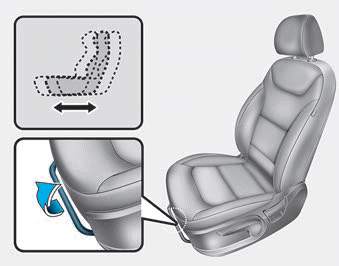
The front seat can be adjusted by using the levers located on the outside of
the seat cushion. Before driving, adjust the seat to the proper position so that
you can easily control the steering wheel, foot pedals and controls on the instrument
panel.
Forward and rearward adjustment
read more


