Hyundai Ioniq (AE): Rear Door / Rear Door Latch. Repair procedures
| Replacement |
| 1. | Remove the rear door module. (Refer to Rear Door - "Rear Door Module") |
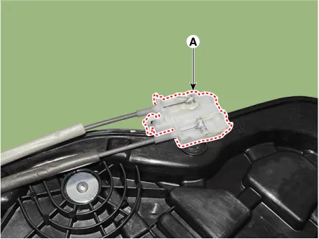
| 2. | Remove the rear door inside handle cage (A).
|
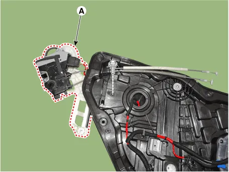
| 3. | Loosen the mounting bolt and remove the rear door latch (A).
|
| 4. | Disconnect the rear door latch connector (A).
|
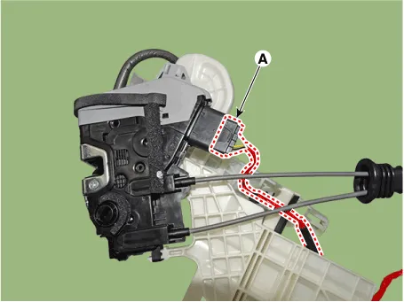
| 5. | Remove the rear door outside handle base (A) by pushing in the lock pins located in the back.
|
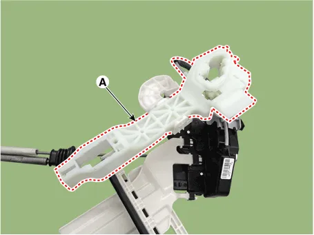
| 6. | Remove the rear door outside handle cable (A).
|

| 7. | To install, reverse the removal procedure.
|

Component Location 1. Rear door latch
Replacement1.Pull down the rear door window glass to the lowest level by pressing the power window glass switch.2.After loosening the mounting screws, remove the rear door belt outside weatherstrip (A).
Other information:
Hyundai Ioniq (AE) 2017-2022 Service & Repair Manual: Repair procedures
Service Point Target Auto Calibration (SPTAC)When you need calibration :– Front view camera is removed and mounted– Replace front view camera with a new one – Windshield glass changed– Front view camera coupler of the windshield glass is deformedService Point T
Hyundai Ioniq (AE) 2017-2022 Service & Repair Manual: Description and operation
System OverviewParking Distance Warning (PDW) is an electronic driving aid that warns the driver to be cautious while parking or driving at low speed. The sensor uses ultrasonic waves to detect objects within proximity of the vehicle.PDW consists of four RPS sensors which are detecting the obstacles and transmit the result separated into three war
Categories
- Manuals Home
- Hyundai Ioniq Owners Manual
- Hyundai Ioniq Service Manual
- Maintenance
- Checking the Coolant Level
- Repair procedures
- New on site
- Most important about car
