
Hyundai Ioniq (AE): BCM (Body Control Module) / Schematic diagrams
| Circuit Diagram |
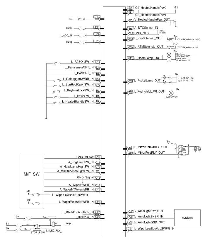
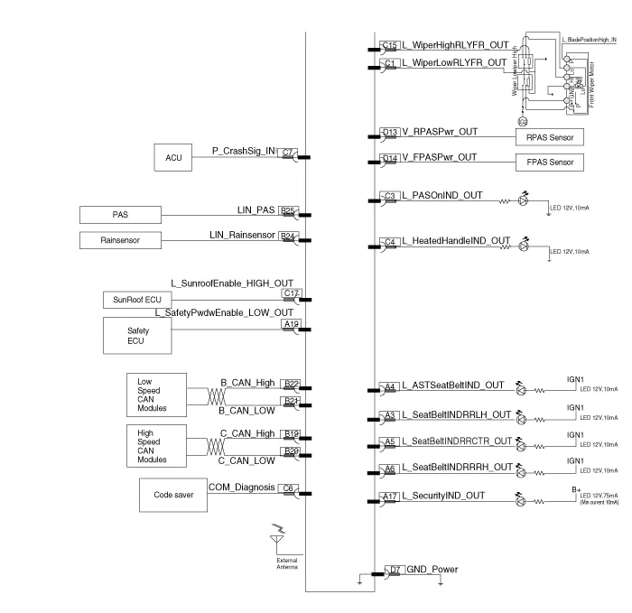
Components NO Connector A Connector B Connector C Connector D 1-Key in switchWiper low relayIGN 1 2-Steering heated switchAuto light groundIG2 Steering heated power 13Rear left seat belt indicator-PAS ON IndicatorIG2 Steering heated power 24Passenger seat belt indicator-Steering heated indicatorIG2 Steering heated power output5Rear centor seat belt indicator--Room lamp6Rear right seat belt indicator-COMGround7--Crash outputPower8-PAS InputCrash output-9Mirror unfolding relayKey inter lock switchAuto light sensor-10-Sunroof open switch NTC SensorRPAS Power11-PAS ON SwitchHead lamp switch (High)FPAS Power12-Multifunction switch groundWiper int vol relayGround signal13Key solenoid-Front wiper switch14--foglamp switch15ATM solenoid output-Wiper relay (High)16--Auto light (Power)17Security indicator-Sunroof enable (High)18Poket lamp output--19Safety powerwindow down (Low)C-Can (Low)-20Key hole illuminationC-Can (High)-21-B-CAN (Low)Front wiper low backupswitch22-B-CAN (High)NTC Ground23 Mirror folding relay output-IGN 124--ACC25PAS-26-Front wiper washer switch27-Blade position28Defogger switchBrake switch29-30-31-32-
DescriptionBody Control Module (BCM) function No Item Description 1Washer Linked Wiper– If the washer switch is pressed ON for 0.
Other information:
Hyundai Ioniq (AE) 2017-2022 Service & Repair Manual: Evaporator Temperature Sensor. Repair procedures
Inspection1.Turn the ignition switch OFF.2.Disconnect the evaporator temperature sensor connector.3.Measure the resistance between terminal "+" and "-" of the evaporator temperature sensor.Specification Evaporator core temperature [°C (°F)] Resistance [KΩ]
Hyundai Ioniq (AE) 2017-2022 Service & Repair Manual: Parking Distance Warning (PDW) Sensor. Repair procedures
Removal1.Disconnect the negative (-) battery terminal.2.Remove the front / rear bumper cover.(Refer to Body - "Front Bumper Cover")(Refer to Body - "Rear Bumper Cover")3.Disconnect the connector (A) from the parking assist sensor.4.Remove the sensor (A) by pulling out both ends of the sensor holder.
Categories
- Manuals Home
- Hyundai Ioniq Owners Manual
- Hyundai Ioniq Service Manual
- Jump Starting
- Brake System
- Hybrid Vehicle Engine Compartment
- New on site
- Most important about car
