Hyundai Ioniq (AE): Low Voltage DC/DC Converter (LDC) / Repair procedures
| Removal |
|

| 1. | Shut off the high voltage circuit. (Refer to Hybrid Control System - "High Voltage Shutoff Procedure") |
| 2. | Remove the air cleaner assembly and air duct. (Refer to Engine Mechanical System - "Air Cleaner") |
| 3. | Remove the ECM & TCM bracket assembly. (Refer to Engine Control/Fuel System - "Engine Control Module") |
| 4. | Drain the coolant of hybrid motor cooling system. (Refer to Hybrid Motor Cooling System - "Coolant") |
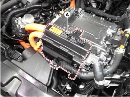
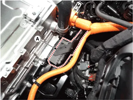
| 5. | Remove the HPCU protector (A) after loosening the mounting bolts.
|
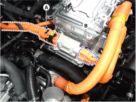
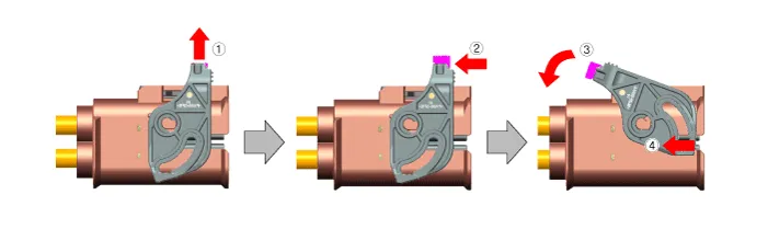
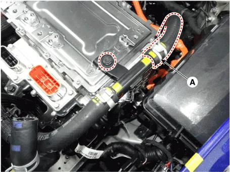
| 6. | Disconnect the motor power cable connector (A) and HSG power cable conector (B).
|
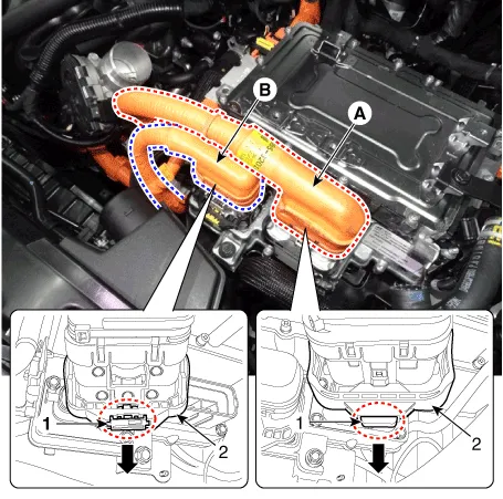
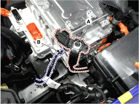
| 7. | Disconnect the power cable (A) [↔ High voltage battery system assembly] and power cable (B) [↔ HSG & Electric A/C compressor].
|

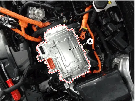
| 8. | Disconnect the HCU & inverter (MCU) connector (A).
|
| 9. | Disconnect the coolant outlet hose & pipe (A) after loosening the mounting bolt.
|
| 10. | Disconnect the LDC power output cable (A) and LDC ground (-) cable (C) after loosening the mounting bolt and nut.
|
| 11. | Remove the HPCU (A) after loosening the mounting bolts.
|
| Installation |
|
| 1. | Install the LDC in the reverse order of removal.
|
| 2. | Refill the hybrid motor cooling system coolant and perform air bleeding by using the GDS. (refer to Hybrid Motor Cooling System - "Coolant")
|

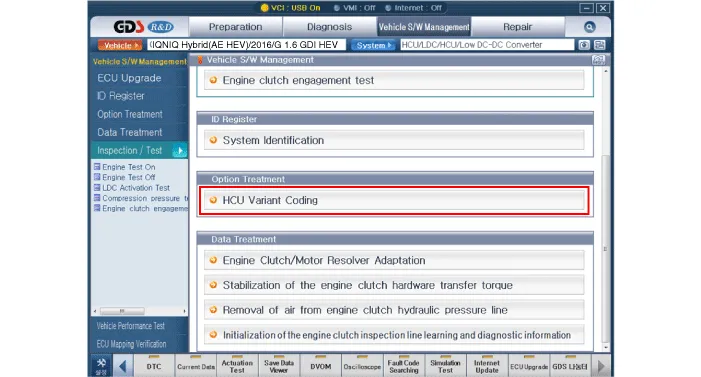
HCU Variant Coding
| 1. | Turn the ignition switch OFF. |
| 2. | Connect the KDS / GDS to Data Link Connector (DLC). Turn the ignition switch ON. |
| 3. | Select "Vehicle, Model year, Engine, System". |
| 4. | Select "Vehicle S/W Management". |
| 5. | Select "HCU Variant Coding".
|
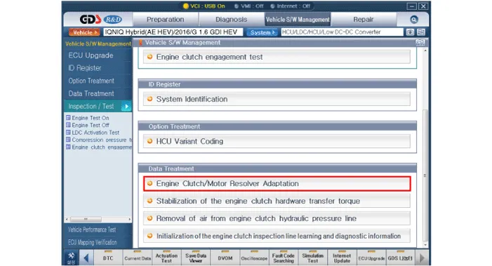
Engine clutch/motor resolver adaptation
| 1. | Turn the ignition switch OFF. |
| 2. | Connect the KDS / GDS to Data Link Connector (DLC). Turn the ignition switch ON. |
| 3. | Select "Vehicle, Model year, Engine, System". |
| 4. | Select "Vehicle S/W Management". |
| 5. | Select "Engine clutch/motor resolver adaptation.".
|
Schematic Diagram
Other information:
Hyundai Ioniq (AE) 2017-2022 Service & Repair Manual: emperature Control Actuator. Components and components location
C
Hyundai Ioniq (AE) 2017-2022 Service & Repair Manual: General safety information and caution
Safety PrecautionPrecautions To Take Before Servicing High Voltage System • Since hybrid vehicles contain a high voltage battery, if the high voltage system or vehicles are handled incorrectly, this might lead to a serious accidents like electric shock and electric leakage.
Categories
- Manuals Home
- Hyundai Ioniq Owners Manual
- Hyundai Ioniq Service Manual
- Engine Control/Fuel System
- Jump Starting
- Transmission Gear Oil. Repair procedures
- New on site
- Most important about car

Copyright © 2026 www.hioniqae.com - 0.0235