
Hyundai Ioniq (AE): Auto Lighting Control System / Schematic diagrams
| Circuit Diagram |
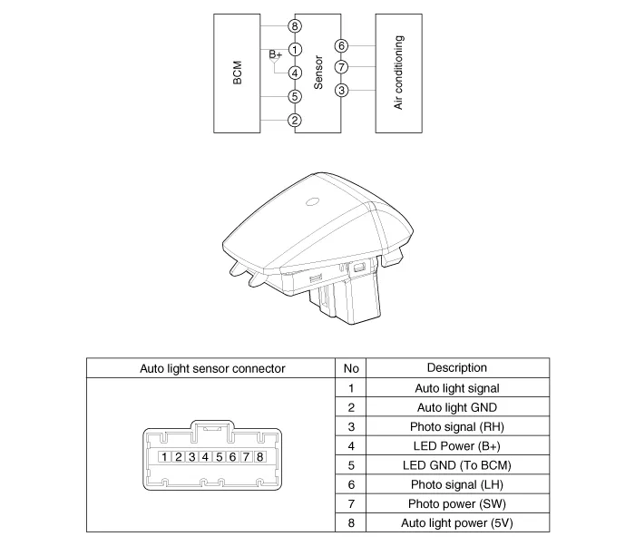
Component Location1. Auto light sensor2. Head lamps3. Lighting switch (Auto)4. Rear combination lamp5. BCM (Body Control Module)
DescriptionIt's a system that uses illumination sensor to automatically turn ON the tail lamp and head lamp based on the change in surrounding environment's illumination condition.
Other information:
Hyundai Ioniq (AE) 2017-2022 Service & Repair Manual: Photo Sensor. Repair procedures
Inspection1.Turn the ignition switch ON.2.Connect the GDS.3.Emit intensive light toward the photo sensor using a lamp, and check the output voltage change.4.The voltage will rise with higher intensive light and reduce with lower intensive light.1. Auto light signal2.
Hyundai Ioniq (AE) 2017-2022 Service & Repair Manual: Description and operation
DescriptionThe smart cruise control system allows a driver to program the vehicle to control the speed and following distance by detecting the vehicle ahead without depressing the brake pedal and the accelerator pedal.1.Cruise speed control : The vehicle maintains the selected speed if there are not vehicles ahead.
Categories
- Manuals Home
- Hyundai Ioniq Owners Manual
- Hyundai Ioniq Service Manual
- Brake System
- Jump starting procedure
- Components and components location
- New on site
- Most important about car
