Hyundai Ioniq (AE): Button Engine Start System / Schematic diagrams
| Circuit Diagram |
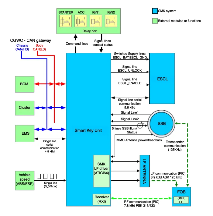
Component Location1. Smart key unit2. Body control module (BCM)3. Interior antenna 14. Interior antenna 25. FOB Key6. Start Stop Button (SSB)7.Door handle & Door antenna8.
DescriptionSystem OverviewThe System offers the following features:– Human / machine interface through a 1-stage button, for terminal switching and engine start.
Other information:
Hyundai Ioniq (AE) 2017-2022 Service & Repair Manual: Front Radar Unit. Repair procedures
Removal1.Remove the front bumper.(Refer to Body - "Front Bumper")2.Disconnect the smart cruise control unit connector (A).3.Remove the smart cruise control nuit assembly (B) from thevehicle after loosening mounting bolts.Installation1.Install in the reverse order of removal.
Hyundai Ioniq (AE) 2017-2022 Service & Repair Manual: Smart Cruise Control (SCC) Switch. Repair procedures
Removal1.Disconnect the negative (-) battery terminal.2.Remove the steering wheel assembly.(Refer to Steering System -"Steering Wheel")3.Remove the steering back cover (A).4.Remove the steering remote control connector (A).5.Remove the steering remote control (A), after loosening the screws.
Categories
- Manuals Home
- Hyundai Ioniq Owners Manual
- Hyundai Ioniq Service Manual
- Maintenance
- DCT(Dual Clutch Transmission) System
- Hybrid Vehicle Engine Compartment
- New on site
- Most important about car
