Hyundai Ioniq (AE): Injector / Schematic diagrams
| Circuit Diagram |
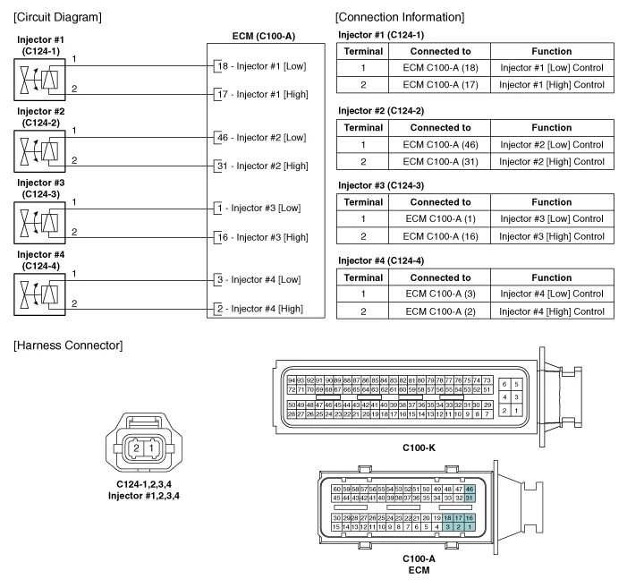
Signal WaveformThe three waveforms below are taken from the #1 and #4 injectors. The top waveform is from the high side (feed side) of the #1 and #4 injectors, while the middle waveform is from the low side (ground side) of the #1 injector and the bottom waveform is from the low side of the #4 injector.
Inspection1.Turn the ignition switch OFF.2.Disconnect the injector connector.3.Measure resistance between the injector terminals 1 and 2.4.Check that the resistance is within the specification.
Other information:
Hyundai Ioniq (AE) 2017-2022 Service & Repair Manual: A/C Pressure Transducer. Repair procedures
Inspection • Before measuring the pressure of the refriferant line, check whether the refrigerant amount is charged in accordance with the specified charging amount.(Refer to Heating, Ventilation, Air Conditioning - "Specifications")1.
Hyundai Ioniq (AE) 2017-2022 Service & Repair Manual: Evaporator Core. Repair procedures
Replacement1.Disconnect the negative (-) battery terminal. 2.Remove the heater and blower assembly.(Refer to Heater - "Heater Unit") 3.Remove the evaporator core cover (A) after loosening the mounting screws.4.Pull out the evaporator temperature sensor (A) from the evaporator core.
Categories
- Manuals Home
- Hyundai Ioniq Owners Manual
- Hyundai Ioniq Service Manual
- Jump starting procedure
- Body (Interior and Exterior)
- Front Disc Brake. Repair procedures
- New on site
- Most important about car
