Hyundai Ioniq (AE): Fuel Pressure Control Valve (FPCV) / Schematic diagrams
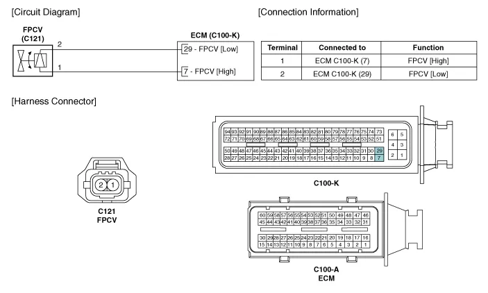
| Circuit Diagram |
Signal Waveform
Inspection1.Turn the ignition switch OFF and disconnect the battery negative (-) cable.2.Disconnect the fuel pressure regulator valve connector.3.Measure resistance between the fuel pressure regulator valve terminals 1 and 2.
Other information:
Hyundai Ioniq (AE) 2017-2022 Service & Repair Manual: Ambient Temperature Sensor. Components and components location
C
Hyundai Ioniq (AE) 2017-2022 Service & Repair Manual: Repair procedures
Removal1.Disconnect the negative (-) battery terminal.2.Remove the tailgate lid trim.(Refer to Body - "TailGate Lid Trim")3.Disconnect the Rear view camera connector (A).4.Remove the Rear view camera assembly after loosening the mounting screws.Installation1.
Categories
- Manuals Home
- Hyundai Ioniq Owners Manual
- Hyundai Ioniq Service Manual
- Hybrid Control System
- General Information
- Suspension System
- New on site
- Most important about car

Copyright © 2026 www.hioniqae.com - 0.0114