
Hyundai Ioniq (AE): Seat Electrical / Seat Heater Switch. Components and components location
Hyundai Ioniq (AE) 2017-2022 Service & Repair Manual / Body Electrical System / Seat Electrical / Seat Heater Switch. Components and components location
| Components |
[Front Seat]
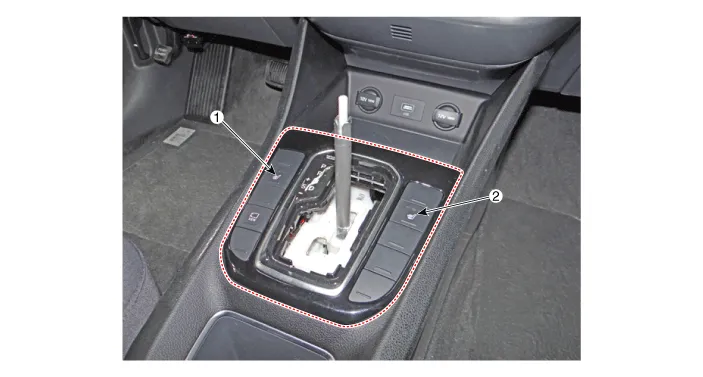
| 1. Driver seater heater switch | 2. Passenger seater heater switch |
[Rear Seat]
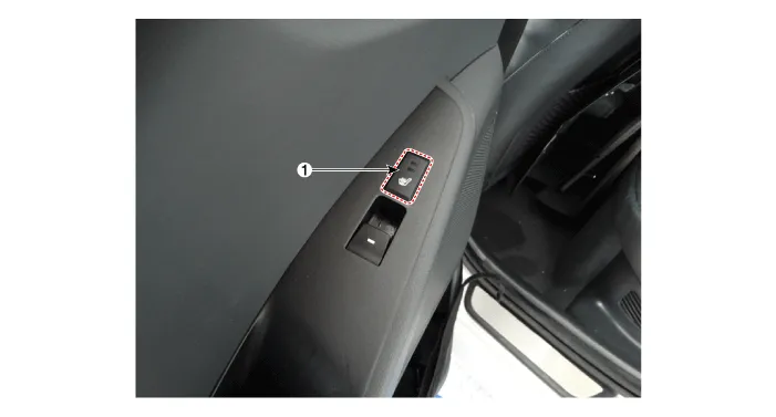
| 1. Seat heater switch |
InspectionFront Seat Heater1.Check for continuity and measure the resistance between terminals No 3 and No 6. Standard value Driver / Assists (cushion + back) : 1.
Circuit Diagram[Front Seat Heater Switch (Driver)][Front Seat Heater Switch (Passenger)][Rear Seat]
Other information:
Hyundai Ioniq (AE) 2017-2022 Service & Repair Manual: Evaporator Temperature Sensor. Repair procedures
Inspection1.Turn the ignition switch OFF.2.Disconnect the evaporator temperature sensor connector.3.Measure the resistance between terminal "+" and "-" of the evaporator temperature sensor.Specification Evaporator core temperature [°C (°F)] Resistance [KΩ]
Hyundai Ioniq (AE) 2017-2022 Service & Repair Manual: Auto Defoging Actuator. Specifications
S
Categories
- Manuals Home
- Hyundai Ioniq Owners Manual
- Hyundai Ioniq Service Manual
- If the 12 Volt Battery is Discharged (Hybrid Vehicle)
- Engine Control/Fuel System
- Troubleshooting
- New on site
- Most important about car

Copyright © 2026 www.hioniqae.com - 0.0177